Shenzhen (ecrazyman) Controller Information

gip_mad said:
To me it looks like these ports are used only to switch the windings based on hall inputs, 3 for high side, 3 for low side; the inverter is a protection so both sides can't be on at the same time; the hardware pwm output (RC2, pin 13) modulates the OR gates to get the switching - so it looks like there is nothing really "emulated" at all. :)
It is still possible to conect to ICD pins anyway.

OK, good observation there, mad gip!

BUT, I still think it is a hack of a solution using 4 extra logic gates only to do part of what a more appropriate micro would be doing alone.

And yes, you are right that you could add in an ICD connector somehow, except for the capacitor on MCLR which might give you trouble.
 
ZapPat said:
BTW knuckles, when are you getting that nice-looking infinion-based controller, and will it be for sale sometime soon? Any info would be great, because I would like to buy a good hackable controller very soon.
Keywin already shipped it to me (and some other folks too). But those darn Beijing Olympic Games has messed up a lot of his client shipments.
He is not happy about that. I think the Games inspired a local punk band also ... http://www.youtube.com/watch?v=F5FLP8RubdU

No word yet on adding communication ports on the new pcb and I hope it won't be a big deal.
 
Knuckles said:
This one http://www.pic16.com/tigao/tig9.doc ends with }
(there are also some neat tig1 thru tig12 docs there too - no clue what they are).

WOW! Looks like ZapPat and gip_mad are some serious programmers. Boy we sure could have used you guys when fechter first identified the critical frequency jitter!
But hey, how about a new project. REGEN! I'll get the prototype boards built with RS232 ports for data output and also a pin connector for programming the MCU.

I am sure the Chinese Infineon pcb vendor will never give us the new MCU code, however. But I may get them to listen if we can develop a regen program that gives us a controlled braking effort. Maybe we can also get a prototype brake lever made that acts just like the hall sensor throttle to vary the degree of braking with a 0 to 5V input.

Now that would be cool! :D

I just noticed this post that slipped by me... It does sound like an interesting possibility, but I would need a circuit schematic for this new controller to see if it would be good for this purpose. Or maybe a couple clear photos of both sides of the board? (like the ones you have here - http://endless-sphere.com/forums/viewtopic.php?f=2&t=4282&p=82710#p82678, but higher resolution please, and try to move wires out of the way as much as possible.
Thanks Knuckles!
 
Hi guys, my last post here for the next 2 weeks! It will be hard to wait so long for news on this project... See you after vacation!
8)
 
I just received my BL7228 controller, And there is a new wire on it : a green one.
Crazyman told me, it is digital speed sensor :D . So that means, can I connect it directly to my Cycle Analyst to the Hall sensor (pin 5) ?
 
piap said:
So that means, can I connect it directly to my Cycle Analyst to the Hall sensor (pin 5) ?
That may be the case. Keywin has added the necessary circuitry for the CA speed function on the stock controller.
He may be doing this as standard now and adding that single wire in lieu of a "full blown" CA connector.

Keywin always proceeds cautiously but the goal (I imagine) is to add the CA to most if not all of the controllers.
Including both the stock controllers and the new Infineons. The Infineons will operate PUMA/BMC motors up to 72V.
But test test test. So feedback is essential to help Keywin have confidence in his controller features.

cheers
 
hi guys, first time poster :D
The extra wire on the controller is indeed a buffered hall sensor output which can be hooked up to CA. Works fine for me.
But then again on my goldenmotor controller (controllers almost identical) the raw hall signal can also drive the CA no probs. Might be depending on ur motor.

As for the rip-off chinese pics, I dont' think so. I used to work in semicon industry in Shanghai, and now I can speaka da chinesey. The economies of ripping off a $1-2 chip and undercutting that price are unlikely.

I'm guessing that the chip is ordered from Mircochip in a bulk pre-programmed lot, and the buyer has requested custom marking.
Again, my GM controller is almost identical and has a marked PIC16F72 chip.
 
ooo 2nd time poster :p
the extra green wire is labelled "BS" on the PCB haha
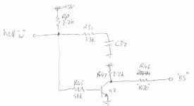
Rp=part of the 4 pin resistor pack on the 3 hall signals.HallBuffer.GIF
 
Can somebody please sum up the findings about this cheap controller? The thread is way too long now.
I'm interested if this controller (after the resonator change, speed mode) is a replacement for my old good crystalite 72V 35A controller .
. I want to drive puma motor at about 50V . Has anybody tried the combination? And lastly what mosfets are in the 600W and 1000W version. Thanks a lot! Nemo
 
nemo said:
Can somebody please sum up the findings about this cheap controller? The thread is way too long now.
I'm interested if this controller (after the resonator change, speed mode) is a replacement for my old good crystalite 72V 35A controller .
. I want to drive puma motor at about 50V . Has anybody tried the combination? And lastly what mosfets are in the 600W and 1000W version. Thanks a lot! Nemo

Me too. XLyte 404. Want 80v at 50+ amps. Would sttle for a bit less. 4110 ? Tnx
 
nemo said:
Can somebody please sum up the findings about this cheap controller? The thread is way too long now.
I'm interested if this controller (after the resonator change, speed mode) is a replacement for my old good crystalite 72V 35A controller .
. I want to drive puma motor at about 50V . Has anybody tried the combination? And lastly what mosfets are in the 600W and 1000W version. Thanks a lot! Nemo

The PUMA solution is the new Infineon controller. The "old" controller described here is good for Direct Drive motors only. The overclock thing is fun and will work for maybe 48V but the point is mute now.

I am posting on the new Infineon today.
See ... http://endless-sphere.com/forums/viewtopic.php?f=2&t=5713#p85483
 
fechter said:
steveo said:
Hey Fechter

I will try placing a 1k resistor accross r7; I am currenting using a 10k + 5k resistor in series with my 100k pot; What resistance should i try in series with my 100k pot?

thanks
-steveo

The value of the fixed resistor in series with the pot will determine the upper limit. I'd try using just the 10k to start and see what you get. If it maxes out too low, then use a lower value.

Hey Fechter

I have tried this mod out; It brings the current limit very low on the lowest setting and on the highest setting it brings it slightly faster. This is perfect to govern speed according to provincial regulations. Even on the highest current setting the controller doesn't feel like its giving more the 20 amps .. (shunt at 45amps)
should i eliminate the resistor in series with the pot?.

P.s. i have used a 50k pot in series and not 100k pot as per this is what i had :S

-steve
 
This is cool because it is exactly want I want to implement on the Infineon pcb. Good work steveo.

-K
 
steveo said:
Hey Fechter

I have tried this mod out; It brings the current limit very low on the lowest setting and on the highest setting it brings it slightly faster. This is perfect to govern speed according to provincial regulations. Even on the highest current setting the controller doesn't feel like its giving more the 20 amps .. (shunt at 45amps)
should i eliminate the resistor in series with the pot?.

P.s. i have used a 50k pot in series and not 100k pot as per this is what i had :S

-steve

You should leave some resistance in series with the pot, maybe at least 1k.
 
fechter said:
steveo said:
Hey Fechter

I have tried this mod out; It brings the current limit very low on the lowest setting and on the highest setting it brings it slightly faster. This is perfect to govern speed according to provincial regulations. Even on the highest current setting the controller doesn't feel like its giving more the 20 amps .. (shunt at 45amps)
should i eliminate the resistor in series with the pot?.

P.s. i have used a 50k pot in series and not 100k pot as per this is what i had :S

-steve

You should leave some resistance in series with the pot, maybe at least 1k.

Hey Fechter

I have left a 10k pot in series with the 50k pot. If i change it to a 1k do you think i will be getting my 45amp limit back?

-steveo
 
I seem to get really strong rotation in reverse but after playing with the wires to get good forward rotation there is no strength to the rotational force.
 
Lessss said:
I seem to get really strong rotation in reverse but after playing with the wires to get good forward rotation there is no strength to the rotational force.

What kind of motor? Sounds like the wiring combination is not right.
 
fechter said:
steveo said:
Hey Fechter

I have tried this mod out; It brings the current limit very low on the lowest setting and on the highest setting it brings it slightly faster. This is perfect to govern speed according to provincial regulations. Even on the highest current setting the controller doesn't feel like its giving more the 20 amps .. (shunt at 45amps)
should i eliminate the resistor in series with the pot?.

P.s. i have used a 50k pot in series and not 100k pot as per this is what i had :S

-steve

You should leave some resistance in series with the pot, maybe at least 1k.

Hey Fechter

I've tried a 1k pot in series with the 50k pot.. when i set the current limit to the max i managed to blow out a phase of mosfets :s... should i try something like a 5k maybe? you think the mod has anything to due with the mosfet blowing?

-steveo
 
Yikes! Is the controller toast?

Maybe I should set up an ecrazy "burnt toast" for "fresh bread" controller exchange program?
(In honor of the destroyer of all controllers ... dirtdad) :shock:

And why so much about lowering the amps? I thought we all want more?
Is it because of "THE MAN" ... :x

cops.jpg
 
steveo said:
Hey Fechter

I've tried a 1k pot in series with the 50k pot.. when i set the current limit to the max i managed to blow out a phase of mosfets :s... should i try something like a 5k maybe? you think the mod has anything to due with the mosfet blowing?

-steveo


Hmm... If the current limit goes too high, it could certainly cause self destruct. I guess 1k is too low.
That earns you a fried guinea pig!
Fried_guinea_pig2.jpg

4.7k is a standard value. It would be nice if you could actually measure the current.
 
fechter said:
steveo said:
Hey Fechter

I've tried a 1k pot in series with the 50k pot.. when i set the current limit to the max i managed to blow out a phase of mosfets :s... should i try something like a 5k maybe? you think the mod has anything to due with the mosfet blowing?

-steveo


Hmm... If the current limit goes too high, it could certainly cause self destruct. I guess 1k is too low.
That earns you a fried guinea pig!


4.7k is a standard value. It would be nice if you could actually measure the current.

Hey

I've tried replacing the mosfet .. and they blew a second time .. so i confirm it the resistance is way to low!!!!.. i even broke a gate resistor and some others that i found replacement for ..

This controller has seen its days.. i've replaced mosfets in it so many times that the mosfet traces on the board are don't even exist ... pretty much all broken

I have gotten the controller working again.. and i have a 5 k or 5 of 1k resistors in series with my 50k :p ..

I will try with 5 k ..

then 4 k ..

my controller has 45amp shunt .. so when i hit near that range with the pot maxed .. i have succeeded!!

Knuckles said:
Yikes! Is the controller toast?

Knuckles i'm interested in that

Maybe I should set up an ecrazy "burnt toast" for "fresh bread" controller exchange program?
(In honor of the destroyer of all controllers ... dirtdad) :shock:

And why so much about lowering the amps? I thought we all want more?
Is it because of "THE MAN" ... :x


I'm interested in the exchange program!!

I just want the controller to be able to go down to legal limit for that just in case scenario for everyone not only myself!!

-steveo
 
Hi all,

I tried my 350w 36v controller with the Bafang I got from eCrazyman and am getting some suspect results. Here are the symptoms of the unloaded hub (not yet in a wheel) :

Starting up is intermittent, rotating the motor by hand and trying again works
Current draw is a crazy 12 amps @ 44v as a result motor wires get warm pretty quick.
Hub speeds up eratically.
Maxes out at around 150rpm

Timing jumper is open and I have rechecked that the loom wire colors match. I also plugged the motor into my existing 36v speedie and it ran beautifully so I am pretty confident the problem lies with the controller. My controller also has an extra blue wire and a connector for a chain ring sensor for a power assist setup.

Are there any easy checks I can perform on the sensor/power leads to make sure there are not open circuit or wired incorrectly (wrong color?) I know my RC motors run in reverse if you swap any of the power wires, can I do the same with the sensor wires without frying the controller.

Hoping for an easy fix rather than having to send it back. I have attached a pix of the controller and attachments.

Cheers
Derek
 
Hi mingonn, wire colors are not standard; you should try every possible combination of phase and hall sensor wires, until the wheel rotates smoothly like it id before.
 
Back
Top