Shenzhen (ecrazyman) Controller Information

Thought it might have been something like that.

Should I start with the sensor wires or the power wires? Will be nice to have it running smoothly on the right controller, geez is ran well.

Derek

Never mind just worked it out, had to swap the blue and green wires around on both power and sensor. One step closer...
 
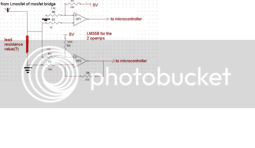
i found a circuit in bldc motor control pcb...for overcurrent detection...im unable to figure out what exactly is happining in it...so please give your valuable suggestions...the microcontroller used is XC846..( if any one could post any document regarding the pin layout and the modules of this microcontroller that will most helpful)...below is the circuit
circuit.jpg


im using cypress microcontroller for bldc motor control in my ebike model...

everything else is sorted out except the overcurrent detection part...for which i traced the circuit which i have shown above from a pcb of some japanese ebike...it has infineon XC846..for which im unable to find any datasheet or pin config details(if u have any material related to them please post)..and i dont have the code...im trying to figureout the logic and hope to implement in my board...

any suggestions are most welcome...
 
See Shenzhen schematic section below:


The top amp is working as a comparator and is looking for current spikes. If the current goes high enough, the voltage across the shunt will rise above the reference for the amp, the output will toggle and send a signal to the MCU to kill the output and display a fault code.

The lower amp is used for the normal current limiter function. It is linear and feeds a signal to one of the A/D inputs (guess). The reference level for this amp is lower than the short circuit detector above, and has a much slower response speed.
 
Hi mingonn, wire colors are not standard; you should try every possible combination of phase and hall sensor wires, until the wheel rotates smoothly like it id before
God that's a relief! - I'm trying to wire one of these bad boys up to a Bafang motor and (untested) LiFePO4 battery - why can't any of these guys send a simple instruction sheet?
I'd really appreciate a little help here... My symptoms...

Got everything wired up as I thought it should be (ie Bafang motor phase & hall sensor wires color-coded) I got a maximum of 6mph unassisted out of my 36v 10ah battery for about 1/2 a mile - with the same problems mentioned by mingonn (ie errattic rotation etc) - the thing sounded like the crack of doom and wouldn't pull me up a hill at all - needless to say I was very disappointed after £250 on a battery, £70 on a motor and £30 odd on controller/throttle etc... Then it made a really ugly noise and the motor cut completely...

I noticed the controller was very hot and naturally assumed I'd toasted it

How loud is the Bafang motor in "proper" operation? Am I OK to switch phase and motor wires around willy nilly until it works?

Also I'm wondering if my "clever" idea to seal the whole deal up (ie battery and controller) in a waterproof box was quite so clever after all... Does the controller need to be exposed to the open air to cool down?
 
Hi Jones,

My heart goes out to you mate. I am using a 350w 36v eCrazyman controller with my bafang. I only ran the motor in a test stand before realising something was wrong, grip_mad pointed me in the right direction.

I tried several incorrect combinations but just swapping the blue and green wires on both the sensor and power wires, worked for me. I hope it was just you LVC that kicked in.

My Bafang is almost silent, a slight hum is all I get all the way to full throttle. It is actually quieter unloaded than my direct dirve brushless hub.

Hope this helps.

Derek
 
It certainly helps me! We took an 8 mile ride today and my wifes Ping cut out early. I think the charger is bad. Bafang performed as usual, which means fine,except for the starting screech and groan. Once above 9 mph it goes fine with minimal heating (except for my poor 25 amp fuse) I gotta get a 30 or 40 just for convenience. Cant wait for Infineon controller to arrive so I can finally test with adequate parameters! Soon, Grasshopper!
other Doc
 
what will be the current sense resistor value...in your diagram R55....i guess its resistance will be low....but...what will be the value?
 
jones, fix your wiring ASAP! You can seriously damage controller and, in extreme situations, the motor windings!! Maybe fetcher can put a note on the very first post about this issue... And we should ask ecrazyman to send at least a mail with instructions, if a printed paper costs too much, to the buyers...

abhimanyu said:
what will be the current sense resistor value...in your diagram R55....i guess its resistance will be low....but...what will be the value?

abhimanyu, please keep the discussion on one topic only.

http://www.endless-sphere.com/forums/viewtopic.php?f=2&t=5713&st=0&sk=t&sd=a&start=45#p91046
 
srry..im new here....i will delete and discontinue...discussing in the other post....

as it is more or less similar to this controller s current sense part...so itll be helpful for me to discuss here...
 
abhimanyu said:
what will be the current sense resistor value...in your diagram R55....i guess its resistance will be low....but...what will be the value?

Ok. Given the hint I gave you on the other post, you should be able to calculate the resistor value by yourself then! If not, just ask! :wink:
 
yea we can calculate it from the requirement..

coming to my present issue...im trying to figure out the material used in the japanese board which i m using for reference...so that i can use same material as resistance on my board..u can help me by suggesting the material which is generally used for these applications
 
I have not measured the actual resistance, but I'd guess it's about 0.002 ohms.

The resistance wire used to make the resistor has about 10 times more resistance than a copper wire of the same size. I do not know the exact composition of the wire or where to get it (other than from another controller).
 
oddjones said:
Hi mingonn, wire colors are not standard; you should try every possible combination of phase and hall sensor wires, until the wheel rotates smoothly like it id before

OK - I was baffled by this until I realised that the black and red wires on the hall sensors are also power wires (at least I assume this is the case - nothing seems to work at all unless they're wired red-red & black-black) which brings down the number of possible combinations of phase and hall wires significantly! (FYI in my case I had to swap green and yellow on both phase and hall sensors).

All seems to be much better now - the wheel is spinning far faster and the motor sounds like a motor rather than a tank (the controller is also remaining blessedly cool).

However, I've not taken it out of it's test rig to try it on the road yet as I have noticed another problem... I can't seem to get it started without rotating the wheel fractionally in the wrong direction (ie in the opposite direction to the motor) - surely this can't be right??? - Once it's started and the throttle is applied then it goes along great guns - the throttle can be varied and the speed varies... until you back the throttle off completely - once the throttle has been closed, opening it again does nothing until the wheel has stopped and again rotated slightly backwards - I've tried swapping hall sensors into all possible configurations (I think) and remain baffled. Any ideas anybody? (My throttle is a 3 LED 36v trigger model purchased from e-crazyman with the controller, wired as suggested in his eBay ad.)

Is this just down to the fact that the wheel is spinning in the air instead of against the road?
 
If the motor does not start by itself, that indicates an incorrect combination.

You are correct about the red and black hall wires. Those are the only ones that are the same no matter what.

You want to test for a combination that will start from any position, and results in the lowest full speed no load current.
 
fechter said:
If the motor does not start by itself, that indicates an incorrect combination.

You are correct about the red and black hall wires. Those are the only ones that are the same no matter what.

You want to test for a combination that will start from any position, and results in the lowest full speed no load current.

Wow - thanks for the speedy response! -

A couple of questions which would really help me track this down...

Firstly - Can I just check this out with you? - I first switched the phase wires around with the hall sensor wires colour-matched - the only combination I got which resulted inanything like a proper speed rotation was yellow-green, blue-blue and green-yellow. I then proceeded to change the hall sensor wires around... Are you saying that the "correct" combination may actually be with a different configuration of phase wires?

Secondly - where am I best measuring the current between? (please be gentle - I'm an electronics dunce and need plain English!)
 
Hi Oddjones,

Watch out a 'Reverse' combination. I fell into this trap when I was fiddilng with my color combinations. The motor would spin up and sound smooth but it was running in reverse. Apply some physical resistance to the hub housing, if the hub stops but you still hear the motor spninning you have it in reverse, this might be the problem.

The sensor wires and the power wire colors should match ie if you power wire combination is Yellow-Green Green-Yellow, your sensor wires should also be set to the same combination.

Derek
 
please see my testing sheet at http://www.oddjones.com/docs/phase-hall-oddjones.xls...

I have tried every phase hall combination there is - both with the 60/120 degree jumper open and closed. I could not get the motor to run with the direction of travel at all ... in every case, in order to make the wheel turn at speed I had to turn it a fraction in the other direction first (as described in my previous post).

Let me first describe what I mean by "forwards" and "backwards"... Here is a picture of my motor in its test rig...

motorrotation.jpg


- I know the wheel is currently in back-to-front(!) - I've tried switching it around every which way to see if it has any effect and it doesn't seem to. please note this is the opposite way around to when I conducted my tests (ie the control wires exit on the left fork, wheras when tested they exited on the right fork, so forwards and backwards have been reversed)

I have no idea which way the motor is supposed to turn! - If I manually turn the motor in the direction shown by the green arrow then the wheel spins freely with no resistance, if I manually spin it the other way there is a mild resistance and a "whirring" noise.

Here's a diagram showing how I've got it wired up - Any wires out of the controller not shown can be assumed to be left open.

wiring-diagram.gif


please help me! I'm utterly bamboozled. (as I think you can probably guess from the wording of this post!) My bike and all its associated clutter have been filling my dining room for over a week now and my wife is beginning to lose patience. Never mind the increasingly cutting jibes of everybody at work who I told about my great new electric bike and how it was going to change my life...

:roll: :roll: :roll:

I notice from I am Oz's post http://www.endless-sphere.com/forums/posting.php?mode=quote&f=2&p=91814 that he included different throttle wiring - could this really make a difference?

I AM 0Z said:
[
THROTTLE
red red
black yellow
green green

I'm clutching straws now guys - put me out of my misery.
 
Your throttle seems to be connected correctly, if the color matches... and the wheel spin. At this point, I would try to check if the motor is defective... First try to measure resistance between every combination of the phase wires: it should be the same. Then, power up the rig, and disconnect the three signal wires from the hall connector. leave the red and black wires connected. Measure the voltage between red and black, ther shoul be at last 5V. then put the black wire of the tester on the black wire of the hall. with the red wire from the tester, measure, one at a time, the three hall wires (thin Yellow, green, blue). They should alternate from 5V to 0V when you slowly rotate the wheel.
Does anyone have some other suggestion?
 
gip_mad said:
Your throttle seems to be connected correctly, if the color matches... and the wheel spin. At this point, I would try to check if the motor is defective... First try to measure resistance between every combination of the phase wires: it should be the same. Then, power up the rig, and disconnect the three signal wires from the hall connector. leave the red and black wires connected. Measure the voltage between red and black, ther shoul be at last 5V. then put the black wire of the tester on the black wire of the hall. with the red wire from the tester, measure, one at a time, the three hall wires (thin Yellow, green, blue). They should alternate from 5V to 0V when you slowly rotate the wheel.
Does anyone have some other suggestion?

Ah... ok resistance equal across all Hall connections (dunno the actual value but it's anout 003 on a scale of 200ohm on my meter)

voltage between Red & black hall sensors 8V ish, each sensor going up to just under 6V then back down to zero as I rotate the wheel (inthe direction of the "red arrow" on the photo - which I assume is forwards, making all my results from last night truly "backwards"!)

So - that seems to prove the Motor's OK - just double checked the throttle - that's definitely as specified throttle(red) - controller(red), throttle(black) - controller(black), throttle(white) - controller(green), throttle(purple) - 36v+ .

What's next?
 
Everything seems ok.... It can be the controller at this point, but it's rare that a brand new controller fail this way. Also, the motor runs good backward, this means that the controller should not have problems.
I'm clueless at this point... Maybe someone can help you better... :?
 
I had the same problem with one of my ecrazyman controllers, never did get it running properly but by wirering it up with this combination it would run,
The only colour code that worked was.
Controller Motor
Blue Yellow
Yellow Blue
Green Green
Hull wires
Black Black
Red Red
Green Green/Blue
Yellow *****
Blue Yellow
I posted about this back on page seven of this thread.
The yellow hull wire didn’t give the same voltage as the green and blue.
 
aaannndddyyy said:
I had the same problem with one of my ecrazyman controllers, never did get it running properly but by wirering it up with this combination it would run,
The only colour code that worked was.
Controller Motor
Blue Yellow
Yellow Blue
Green Green
Hull wires
Black Black
Red Red
Green Green/Blue
Yellow *****
Blue Yellow
I posted about this back on page seven of this thread.
The yellow hull wire didn’t give the same voltage as the green and blue.

Yup - that's it exactly. So what can I do? I don't want to put up with this - I've just spent a whole heap of cash (and time) - Do you reckon it's definitely the controller? (Did you get the motor to run smoothly with another controller?) - If so, can I send the controller back and get a replacement? What do people think? I've heard Knuckles and co on here talking up "customized" versions of this controller - If it is the controller, well at least it's the cheapest part of the setup I suppose - Can I get a better controller for my motor / battery / throttle combination (ie one which'll give me higher speed perhaps? :D )
 
OddJones,

Sorry about the stupid post that I deleted. If you actually rode it, however slowly, the motor is mounted on the bike in the proper direction. Yes is should freewheel when you spin it forward (that's like you are coasting along or pedaling only, so you don't want the motor resistance).

No, you do not want to controller in a sealed box. It needs to dissipate heat. You can make it water resistant quite easily. I rode mine (the 72v version) on the beach every day for a week back in July, with wet salty water spraying it, with the only precaution being duct tape to prevent spray getting to the wire end. The only effect is that the screws are now a bit rusty.

Now to your problem. Am I to understand that you have it running fine with good speed and the motor sounding nice and smooth at all speeds, but it needs a little backward roll to get the controller to kick in? If so, then it sounds like your initial ride with the incorrect wiring did some damage to the controller. When an electric motor is sounding like the "crack of doom" and you keep going until "it made a really ugly noise and the motor cut completely", then I would consider you to be very lucky if you didn't damage at least the controller by riding it with the wires connected incorrectly.

If it's now running well and spinning the wheel forcefully, the the wiring sounds correct, but that little backwards roll requirement is saying that it first needs a magnet to pass a hall sensor to get going. Something is definitely wrong. My guess would be that you fried something in the controller. Since it still works at all, then it's probably something small. My suggestion would be to get with Knuckles and explain the symptoms and history to get the problem diagnosed, and get you riding. If it "goes great guns" with the motor no ragged noises, only the whirring of the gears, then the wiring sounds correct, so I hope you made note of the combination. Don't spend a bunch of time going crazy with wiring combinations until you have a diagnosis.

Good Luck with it. All the frustrations will make it all the more sweet once you get it running properly. On my first ride with a hub motor, I made it less than 10ft before the dropouts snapped and the axle spun breaking the wiring harness, and I thought I had sufficient torque arms, so if it's just the controller you got off easy. I don't see torque arms on yours, and with a front geared hub that's just begging for a serious accident.

John
 
That does sound strange. Not sure what it could be. Has the motor worked with a different controller? If the halls check out OK, then the only other possible motor problem would be a shorted winding. If this was the case, there would be a lot of drag in the non freewheeling direction. Some drag is normal, but a shorted winding would be like brakes.

Could be a bad controller too. Warranty?
 
Back
Top