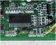
Shenzhen (ecrazyman) Controller Information

ZapPat said:
I can't agree with this first part at all, fetcher, since by shorting the motor like you suggest, you will not be getting ANY regen at all, this could merely be usefull to slow down the motor by dumping the energy into the FETs in case of an emergency or something (could use the top or bottom FETs for this BTW). Regen is done merely by lowering your duty cycle to a point where energy starts flowing backwards from your motor into your battery pack. You are now taking a lower voltage from the motor, and steping it up to a high enough voltage to start recharging your pack. There are a number of factors which influence the efficiency of such a system, a number of them external to your controller. Like charge acceptance of the battery for one... Supercaps would help greatly with this problem, but when oh when will they pop into existance?

Lowering the duty cycle will do nothing to make the motor regen into the batteries. If the motor is turning at a speed that is lower than its no-load speed, the back EMF will be lower than the battery voltage, and no regen will be possible regardless of duty cycle.

By shorting the motor, the current in the motor windings will start out at zero, then rise quickly to a level where it becomes constant, and a function of the motor winding resistance and the back emf of the motor. If you release the short before the windings reach steady state, the magnetic field collapses, generating a very high voltage spike which will be circulated back to the batteries by the body diodes in the FETs. By controlling the duty cycle of this shorting, you can vary the average braking current. You can get power back into the batteries even though the motor is going much slower than its no-load speed. This works exactly like a boost switching converter, except we're using the motor windings as the inductor.

On my Zappy, I was able to regen into the batteries all the way down to under 5mph. It works.
 
But code is missing also from your document... :(
You see the last lines:
Code:
void interrupt INTS(void)
{
 if(RBIF==1) {RBIF=0;sample();}
 else if(ADIF==1) AD();
else if(INTF==1) {shutdown=1;INTF=0;} //刹车中断来,置刹车标志

there is code missing... Every function should end with a } !

Nice to have the schematics by the way. I don't understand what Q, L and X inputs connected to pins 11, 12, 14 are for. Do you have any hints?
 
fechter said:
By shorting the motor, the current in the motor windings will start out at zero, then rise quickly to a level where it becomes constant, and a function of the motor winding resistance and the back emf of the motor. If you release the short before the windings reach steady state, the magnetic field collapses, generating a very high voltage spike which will be circulated back to the batteries by the body diodes in the FETs. By controlling the duty cycle of this shorting, you can vary the average braking current. You can get power back into the batteries even though the motor is going much slower than its no-load speed. This works exactly like a boost switching converter, except we're using the motor windings as the inductor.

On my Zappy, I was able to regen into the batteries all the way down to under 5mph. It works.

OK, this sounds cool! I did not know of this trick to do regen with a three phase motor. Altough I had something else in mind.

fechter said:
Lowering the duty cycle will do nothing to make the motor regen into the batteries. If the motor is turning at a speed that is lower than its no-load speed, the back EMF will be lower than the battery voltage, and no regen will be possible regardless of duty cycle.

Hum... unless I'm totaly loco, this is not true when you are operating your motor with a 4 quadrant modulation PWM scheme. Let me see, I'll look for this doc I have about this...


You are thinking in terms of simple 2 quadrant control, where regen is not possible without your trick.

Each phase is only a top switch and a bottom switch (to batt+ and batt-), and there are a number of ways to control these switches. When you want regen you have to actively switch both top and bottom at high frequency, instead of leaving one on and pulsing rapidly the other like you are probably talking about.

Now I don't know if the crazyman controller uses this or not, I don't have one.

I would think that the golden motors regen controller uses this 4 quad, though, but I'm still not sure ( I may order one).

Also FYI a synchronous buck converter acts as a boost converter when seen from the other side. Think of it...
 

Attachments

  • hitachi tech_tips06 (about 4 quadrant BLDC control).pdf
    209.7 KB · Views: 85
This one http://www.pic16.com/tigao/tig9.doc ends with }
(there are also some neat tig1 thru tig12 docs there too - no clue what they are).

WOW! Looks like ZapPat and gip_mad are some serious programmers. Boy we sure could have used you guys when fechter first identified the critical frequency jitter!
But hey, how about a new project. REGEN! I'll get the prototype boards built with RS232 ports for data output and also a pin connector for programming the MCU.

I am sure the Chinese Infineon pcb vendor will never give us the new MCU code, however. But I may get them to listen if we can develop a regen program that gives us a controlled braking effort. Maybe we can also get a prototype brake lever made that acts just like the hall sensor throttle to vary the degree of braking with a 0 to 5V input.

Now that would be cool! :D
 
gip_mad said:
But code is missing also from your document... :(
You see the last lines:
Code:
void interrupt INTS(void)
{
 if(RBIF==1) {RBIF=0;sample();}
 else if(ADIF==1) AD();
else if(INTF==1) {shutdown=1;INTF=0;} //刹车中断来,置刹车标志

there is code missing... Every function should end with a } !

Nice to have the schematics by the way. I don't understand what Q, L and X inputs connected to pins 11, 12, 14 are for. Do you have any hints?
Good observation, mad gip, there is a missing bracket.

However I think it's fairly safe to assume they forgot to copy the last bracket, but the code would logicaly stop here with the sleep mode possibility.

As for Q,L and X I would assume they are the hall sensor inputs.
 
Knuckles, do you have the schematic of that new nice looking controller you posted a photo of?
It looks simpler somehow than the regular crazyman controller I am looking at. All those logic gates and driver components look like big confusion!
It does tell me something though: having this many parts to assemble into such a cheap controller can only be economicaly viable when done in a country where labour costs are relatively small. :( I do wonder why they didn't design it using a PIC18F motor control micro instead of a non-specialized PIC16? Many features implemented in hardware on the crazyman schematic could be replaced by the bigger PIC's specialized hardware. It also does hardware math multiply, great for math speed.
 
Well, looking at the other code posted, it looks like only one bracket was missing! :) I asked because it could have missing 1000 lines of code, or just the bracket; in this case it was only the bracket :wink: .
It doesn't necessary mean that, with the sleep command, the program will end! That is a function, and once it is finished,it will return to the line of code after the one that called it.
I don't think that QXL are the sensors, because there are 3 inputs that are more plausible on the right UVW connector (pins 15,16,17) for the halls. For the regen project... I'm sorry, but I don't have a clue on how regen works! AND, I don't have a clue on how to program that Infineon part... :cry: It will take a lot of time (that I don't have) and effort (I have plenty of it! :wink: ) for me just to get started, so I must pass on this. I'm always here if you need any help anyway! That is the same reason why I asked for you to ask to your engineers to implement the serial port... I would have asked FIRST to give me the code if only I was able to program it myself... No problem if it was a PIC!
Anyway, tell them this: we can do nothing with their code, THEY manufacture these things at ridiculous prices, we can NEVER compete with them... Knowing china people, the code should be very similar to the Infineon AppNote with minor modifications anyway, so we can start with it. I'll look around to see if it is that hard to program these MCUs.

PS: oh my god, I read again that post and it sounds HORRIBLE... I hope my english doesn't offend too much your senses! :oops:
PPS.: I'll be on vacation in an off-limit no-internet location from 28 Jul to 9 aug, so don't expect any update from me in that period!
 
ZapPat said:
OK, this sounds cool! I did not know of this trick to do regen with a three phase motor. Altough I had something else in mind.

fechter said:
Lowering the duty cycle will do nothing to make the motor regen into the batteries. If the motor is turning at a speed that is lower than its no-load speed, the back EMF will be lower than the battery voltage, and no regen will be possible regardless of duty cycle.

Hum... unless I'm totaly loco, this is not true when you are operating your motor with a 4 quadrant modulation PWM scheme. Let me see, I'll look for this doc I have about this...


You are thinking in terms of simple 2 quadrant control, where regen is not possible without your trick.

Each phase is only a top switch and a bottom switch (to batt+ and batt-), and there are a number of ways to control these switches. When you want regen you have to actively switch both top and bottom at high frequency, instead of leaving one on and pulsing rapidly the other like you are probably talking about.

IMO. Most of the BLDC controllers for ebikes use simple 2 quadrant PWM scheme for low switching loss.
 
Ok, I took a look at the docs you posted, they look like A) class exercise or B) a list of examples to learn PIC programming. There are chapter numbers on top of documents. Also, there are TOO many comments, which is a thing that programmers SHOULD do but NEVER do, and you can find this amount of comments only on class papers or academic textbooks. This doesn't mean that it is not our code anyway! :shock:
I assume that the original document is: http://vip.6to23.com/dangdang/pdf/PIC%B5%A5%C6%AC%BB%FA%B1%E0%B3%CC%CA%B5%C0%FD.pdf
A translation of our code is here: http://translate.google.it/translat...2006/11123.html&sl=zh-CN&tl=en&hl=it&ie=UTF-8
 
gip_mad said:
Ok, I took a look at the docs you posted, they look like A) class exercise or B) a list of examples to learn PIC programming. There are chapter numbers on top of documents. Also, there are TOO many comments, which is a thing that programmers SHOULD do but NEVER do, and you can find this amount of comments only on class papers or

I actually dissagree with you here, mad gip, because I know how memory works, and well commented code is easy to get back into after a year or more of not using it.

Additionnaly, any open source code should also be well commented IMHO, as it helps everyone in the group undertstand what's going on, even if they are new to the program.

It's not so much the quantity, but more the quality that counts anyways...
 
gip_mad said:
Ok, I took a look at the docs you posted, they look like A) class exercise or B) a list of examples to learn PIC programming. There are chapter numbers on top of documents. Also, there are TOO many comments, which is a thing that programmers SHOULD do but NEVER do, and you can find this amount of comments only on class papers or academic textbooks. This doesn't mean that it is not our code anyway! :shock:
I assume that the original document is: http://vip.6to23.com/dangdang/pdf/PIC%B5%A5%C6%AC%BB%FA%B1%E0%B3%CC%CA%B5%C0%FD.pdf
A translation of our code is here: http://translate.google.it/translat...2006/11123.html&sl=zh-CN&tl=en&hl=it&ie=UTF-8
Did you notice that the doc is titled "AVR microcontroller control of the electric bicycle drive system"?
A funny name for a program written for a PIC micro, no? :eek:
The code looks PIC16-like though, with similar register names, so maybe it's ported code from the AVR?
 
Well, maybe you have never took a look at a linux source... :D Reminds me of this: http://forums.xkcd.com/viewtopic.php?f=11&t=11935
:lol:
i++; //add 1 to i

/.... tons of other code, completely without comments ..../

int b = 0; //initialize b

/.... tons of other code, completely without comments ..../
double CrazyComplexFunction(...) // Trust me - it works
I agree with the usefulness of comments, I was saying that actually programmers, in real life situations, comment very few code. We all know that is a good practice, and every book teach you that you should always comment, but usually people doesn't comment very often. Maybe it's different for you.... Good for you! :p
The AVR thing, I think that this was a post regarding a port of that code to AVR. I did a search for the code that k. posted, and that was (oddly) one of the result, and (oddly) the one that I choose to run through google translator. It's the same code anyway. :)
 
If I had a programmer interface, could I read the code out of an installed chip? The board has connection points for an in-system programmer.

I would trust this way more than what we have now.
 
fechter said:
If I had a programmer interface, could I read the code out of an installed chip? The board has connection points for an in-system programmer.

I would trust this way more than what we have now.

Only if code is not protected. Or if you are a good micro hardware hacker, but I'm sure not, even for PICs I would have no idea how to hack a code protected chip.
 
Hehe, it's possible, but you need acid to open the chip. :) The source is almost useless as it is anyway, it is in assembly format and while perfectly feasible it will be toooo boring to modify it! :roll:
Btw, having the schematics it should not be too hard to edit the basic code we have and verify if it works. As Madonna says, "So many work, so little time!" :)
 
gip_mad said:
Hehe, it's possible, but you need acid to open the chip. :) The source is almost useless as it is anyway, it is in assembly format and while perfectly feasible it will be toooo boring to modify it! :roll:

Sounds cool, and very good point about the assembler! I've known companies put so much trouble into reverse-engineering some code, it would have been faster and so much better to start fresh.

Btw, having the schematics it should not be too hard to edit the basic code we have and verify if it works. As Madonna says, "So many work, so little time!" :)

This is true, but I would much rather use my own code made for the pic 18F2331 because things would be simplified much. Of course for the people only wanting to easily mod an existing controller they can buy ready-made, then I guess we have to stick with the PIC16 and the additionnal hardware that comes with it in the crazyman. That photo of the infinion based board looks simpler too, but I'm not too sure.

Does anyone own both a microchip in circuit debugger (ICD) AND a crazyman controller? I only have an ICD2, no crazyman sadly. Maybe the chip isn't even code protected, who knows? I'ts only a couple wires to connect the ICD. I'll have to check the PIC16 datasheet to check which ones. Even if it is code protected, I am pretty sure we can just bulk erase and start fresh with C compiled code, similar to that open source one supposedly already in it.

Does anyone have a close-up picture of of the micro in the crazyman, BTW?
 
It's labeled HA3089.

It clearly has connections for in-system programming.

I have an ISP interface for Atmel chips :(
HA3089 Microcontroller.jpg
 
fechter said:
It's labeled HA3089. [/attachment]
I think the HA3089 is a Chinese PIC 16F clone. There are no English specs on it that I can find.
FWIW. Rich suggested the PIC 18 (40-mhz MCU) many moons ago (private email). But at least the days of $300 e bike controllers are over.
Plus we may have the PUMA solution at 72V and "Ludicrous Speed" (with new Infineon) which I guess is a good thing.

But hey. I still want controlled (highly efficient) regen. And the Easter Bunny too! :shock:
 
I have two ICD2s, AND the ecrazyman, but I have to disassemble all the wiring on the bike to get to it... Plus I'm leaving for vacations on sunday... Sorry but you'll have to wait if you want mine :roll:

Since the PICS are both 28 pin, we can see if we can adapt the 18F instead of the "original". The pwm lines seems to be compatible, and we just have to bridge the logic ports. Nah, I think it's better to learn to progrm the infineon part.

I have a theory: maybe the 18F pic is too complex for china to clone it? :lol: :roll:

Interesting reading: http://www.bunniestudios.com/blog/?page_id=40 and, before you ask: no, it's not worth the trouble :roll: .
 
(gotta be politically correct)
 
Looks like the chip from "Terminator". :shock:
 
After looking at that photo (thanks fetcher!) and the circuit schematic for the crazyman, it is apparent that it does not have provisions for microchip's ICD2. It would be using pins 27 and 28 for clock and data, but these pins are being used as [hacked] PWM outputs. I say "hacked", because it is just regular port B pins being used, not any specialized PWM module as this PIC16F72 does not have any.

This limitation also explains the relatively complex hardware (ie logic gates and discrete parts) being used to control the FETs.

BTW knuckles, when are you getting that nice-looking infinion-based controller, and will it be for sale sometime soon? Any info would be great, because I would like to buy a good hackable controller very soon.
 
To me it looks like these ports are used only to switch the windings based on hall inputs, 3 for high side, 3 for low side; the inverter is a protection so both sides can't be on at the same time; the hardware pwm output (RC2, pin 13) modulates the OR gates to get the switching - so it looks like there is nothing really "emulated" at all. :)
It is still possible to conect to ICD pins anyway.
 
Wow, a Google bot, it's the first time I spot this! :shock:

Edit: Yahoo too! Were famous! :lol:
 

Attachments

  • google bot2.PNG
    google bot2.PNG
    32.1 KB · Views: 3,213
  • yahoo bot2.PNG
    yahoo bot2.PNG
    25 KB · Views: 3,209
Back
Top