Captain Qwark
100 µW
Introduction
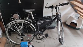
First of, this is my first DIY electric anything project, so my apologize if I get things confused or completely wrong. I'm building a cheap 500w electric bike. I thought I chose all the right components but now 2 controller later and I still can't get this simple build done. I'll summarise everything I used as detailed as possible. For people wanting to buy my build, links are down below.
Measurements & facts
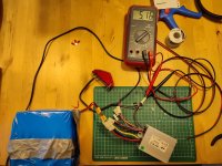
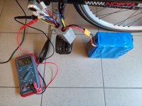
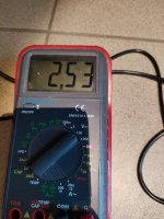
When I hand spin the motor I do receive a voltage measurement and this seems to tell me the motor is fine.
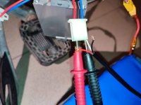
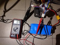
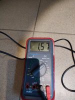
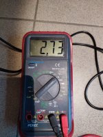
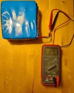
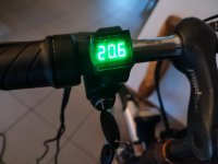
When I measure the voltage from the battery I receive a stable 29.1V. I can't test the current as it will blow my 10A fuse in my multimeter. Uses an XT60 connector.
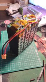
Battery is made with 2x8mm thick 99.6% nickel strips which are spot-welded. Both poles are connected with 14AWG tinned copper wire.
Issues
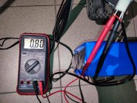
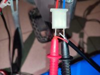
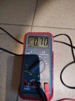
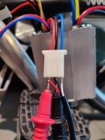
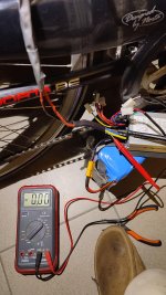
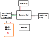
Problem 1: I don't receive any voltage with the multimeter when increasing the throttle.
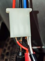
Problem 2 (maybe): I can't hear any "click" in both cases when switching the key. The display also doesn't turn of when ignition is off. I used a wire to bridge the contact in between the positive and negative of the power lock on the motor controller which should simulate the ignition turning on, still nothing.
Conclusion
So I assume I must be overloading the motor controllers, causing the fuses of mosfet's to immediately break or the power switch simply doesn't work (I doubt it). Perhaps even the throttle. I'm hoping someone could enlighten me or simply show me all the things I did wrong. I understand that buying everything from AliExpress comes with it's risks but as I'm just a high school student, my budget is quite restrained. The whole project is currently under 250 euro's (100 euro's on batteries).
Complete Project Item List & Buy Links (all from AliExpress unless stated)
First of, this is my first DIY electric anything project, so my apologize if I get things confused or completely wrong. I'm building a cheap 500w electric bike. I thought I chose all the right components but now 2 controller later and I still can't get this simple build done. I'll summarise everything I used as detailed as possible. For people wanting to buy my build, links are down below.
- DIY Battery
- 7 series - 8 parallel
- 2900mAh - 5.8A - 3.6V
- Voltage of the storage system = 25V
- Current of the storage system = 46.4A
- Capacity of the storage system = 23Ah = 584Wh
- Data Sheet
- BMS
- Continuous working current = 20A
- Charging current = 10A
- Brushed Motor
- 500W 24V DC
- Rated current = 26.7A
- Data Sheet (I have ZY1020 model but seems to be the same)
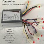
- Motor Controller
- Rated Voltage = 24V
- Under-Voltage Protection = 20+-0.5V
- Speed Regulator = 1-4V
- Match Motor = 500W
Measurements & facts
When I hand spin the motor I do receive a voltage measurement and this seems to tell me the motor is fine.
When I measure the voltage from the battery I receive a stable 29.1V. I can't test the current as it will blow my 10A fuse in my multimeter. Uses an XT60 connector.
Battery is made with 2x8mm thick 99.6% nickel strips which are spot-welded. Both poles are connected with 14AWG tinned copper wire.
Issues
Problem 1: I don't receive any voltage with the multimeter when increasing the throttle.
Problem 2 (maybe): I can't hear any "click" in both cases when switching the key. The display also doesn't turn of when ignition is off. I used a wire to bridge the contact in between the positive and negative of the power lock on the motor controller which should simulate the ignition turning on, still nothing.
Conclusion
So I assume I must be overloading the motor controllers, causing the fuses of mosfet's to immediately break or the power switch simply doesn't work (I doubt it). Perhaps even the throttle. I'm hoping someone could enlighten me or simply show me all the things I did wrong. I understand that buying everything from AliExpress comes with it's risks but as I'm just a high school student, my budget is quite restrained. The whole project is currently under 250 euro's (100 euro's on batteries).
Complete Project Item List & Buy Links (all from AliExpress unless stated)
- Motor controller 1
- Motor controller 2 / eBay
- Motor eBay
- Motor Chain
- Rear Wheel Sprocket (gear calculator)
- Electric Cable Heat Shrink
- Wire Connector Kit
- 29.4V 5A Battery Charger
- Throttle Control
- Throttle Key Switch
- Battery (range calculator)(configuration calculator)
- BMS
- 18650 batteries depending on your choice and needs (you will probably have to look for a different Battery Charger, BMS,...)
- Battery Insulation
- XT60 Connector
- 2 Core Thick Cables
- 18650 Modular Battery Holders
- Battery Heat Shrink
- XT60 -> Battery charger adaptor
- Nickel Strip
- Spot welder
- High Temperature Heat Tape
Attachments
-
 IMG_20240308_211251.jpg112 KB · Views: 11
 -
 IMG_20240222_130120.jpg708 KB · Views: 11
 -
 IMG_20231224_000237.jpg501.5 KB · Views: 10
 -
 IMG_20240210_004247.jpg987.8 KB · Views: 11
 -
 DIY E-Bike Schematic.png17.1 KB · Views: 11
 -
 IMG_20240309_173437.jpg341.2 KB · Views: 7
 -
 Motor Controller 1.jpeg32.3 KB · Views: 4
Last edited:
")