Simple ebike 'fuel gauge'

That is a great project!
I think there is quite a need for something simple (inexpensive) like this.
I love the meter, I've never seen one like that before.
I've been looking at the TI BQ20xx series battery meter chips, which are similar.
For an electric motorcycle or car, the current will be much higher, but you would just use a lower resistance shunt. Ideally the meter would be self-calibrating like the TI chips.
 
otas said:
I would like to register my interest in making this fuel gauge meter. I hope that I have something positive to bring to this group/concept. I can make a small batches of thingymigics. Hope it is not like taking coal to Newcastle, with so many interested parties. I have had the LED bar display in my plane as a MAC trim position display. I did not like it for two reasons. Poor visibility in the sun and relative small dimensions. I made discrete LED display of the trim and electric flap position indicator. I preffer spacing of the individual LEDs with gaps, to achieve registration in the peripheral vision rather than the need to look at it directly. And I use the Picaxe in some of my light strobe devices.

So here is an outline of my concept:
1. discrete multicolour 10 LED dispaly of the current - green, yellow, red
2. discrete multicolour 10 LED display of the power remaining - green, yellow, red
3. separate yellow LED to indicate less than 10% power remaining
4. reset button to press after the battery charge
5. 4-6 wire connector RJ11 or RJ14
This would be mounted in a small box say 50x50x20mm or 50x80x25 on handlebars with wire going to the battery/controller.
The Voltage would be selected by option link to say 24, 36, 48 and 72V with trimpot for a fine adj.
The Current gain will have trimpot for the max. scale adjustment.

There will be a separate current shunt inserted in the battery connection to reduce the DIY demand to tap the existing controller shunt. The purists, who would not like to loose some 0.15V on the external shunt will be able to solder sensor wires directly onto the controller shunt. This way the need for a programming the Picaxe chip would be minimised and the final configuration easily done DIY.

I would appreciate your comments to the general concept, what to add, or take away.
I am not very fast, and I have already few projects going on, so I cannot promise to have it ready yesterday.
otto

This sound good, and im sure if the price is right they will be snapped up ( what sort of price are you talking for a finished product ? ).. Would you include a lipo monitor ? as I think this would be beneficial.
 
gwhy! said:
This sound good, and im sure if the price is right they will be snapped up ( what sort of price are you talking for a finished product ? ).. Would you include a lipo monitor ? as I think this would be beneficial.

What do you exactly mean by a lipo monitor? Do you mean a voltmeter? I cannot quantify price at this stage, I am looking at an alternative to INA122, perhaps just an op-amp. and other ways to save money. With 10% display resolution it may be an overkill to use precission instrumentation amp. What do you think Jeremy?
otto
 
otas said:
gwhy! said:
This sound good, and im sure if the price is right they will be snapped up ( what sort of price are you talking for a finished product ? ).. Would you include a lipo monitor ? as I think this would be beneficial.

What do you exactly mean by a lipo monitor? Do you mean a voltmeter? I cannot quantify price at this stage, I am looking at an alternative to INA122, perhaps just an op-amp. and other ways to save money. With 10% display resolution it may be an overkill to use precission instrumentation amp. What do you think Jeremy?
otto

something along the lines of the lipo monitor that I posted a pic of, i.e steady led if voltage is above 40v and flashing led if below 40v' ish for a 44.4v lipo setup. A standard op-amp I think will not be to good in this application for a number of reasons, but a cheaper instrumentation amp will do the job just as good.

edit: It should be quite easy to incorporate into Jemery's exsiting code if a larger picaxe chip was used.
 
gwhy! said:
something along the lines of the lipo monitor that I posted a pic of, i.e steady led if voltage is above 40v and flashing led if below 40v' ish for a 44.4v lipo setup. A standard op-amp I think will not be to good in this application for a number of reasons, but a cheaper instrumentation amp will do the job just as good.

edit: It should be quite easy to incorporate into Jemery's exsiting code if a larger picaxe chip was used.

What about 10 LED voltmeter with a magnified scale, e.g. max. at 4.2V and minimum 3.7V per cell, spreading the difference of 0.5V x12 cells = 6V accross the 10 LEDs. That can be worked out by Picaxe A/D part. The op-amp replacement was meant for replacement of the instr. op amp for the current measurement, not voltage. Isn't the actual fuel gauge with yellow 10% "reserve" showing the power left more usefull than just voltage indicator, or you want the voltage ind. as well as the earlier mentioned meters?
otto
 
wineboyrider said:
No offense to anyone, but isn't this close?
http://www.hobbycity.com/hobbycity/store/uh_viewItem.asp?idProduct=6232

Although, not designed for ebike use?

Of course, if there is anything suitable availble, I will rather buy it and forget about making it. This Cellmeter is a voltmeter. Period. If that is all you want, OK. It does not give you indication of the current drawn and power left as in capacity, rather than plain volts.
otto
 
otas said:
I cannot quantify price at this stage, I am looking at an alternative to INA122, perhaps just an op-amp. and other ways to save money. With 10% display resolution it may be an overkill to use precission instrumentation amp. What do you think Jeremy?
otto


I only used the INA 122 because I had a few already, left over from another project. It was the only device I had to hand that worked on a single 5V rail, had a fairly low offset drift and had a common mode input range that includes the 0V rail. The latter point is important, as the voltages being sensed are only a few mV above 0V.

If you can find a cheaper device that will do this then I'm sure it'll work OK, as you say, you don't really need the precision (although be aware that Ah errors are cumulative, so you need a fair bit better than the display resolution).

Jeremy
 
Jeremy Harris said:
otas said:
I cannot quantify price at this stage, I am looking at an alternative to INA122, perhaps just an op-amp. and other ways to save money. With 10% display resolution it may be an overkill to use precission instrumentation amp. What do you think Jeremy?
otto


I only used the INA 122 because I had a few already, left over from another project. It was the only device I had to hand that worked on a single 5V rail, had a fairly low offset drift and had a common mode input range that includes the 0V rail. The latter point is important, as the voltages being sensed are only a few mV above 0V.

If you can find a cheaper device that will do this then I'm sure it'll work OK, as you say, you don't really need the precision (although be aware that Ah errors are cumulative, so you need a fair bit better than the display resolution).

Jeremy

Yikes! the INA122 is a spendy little bugger. Nice specs though.
I suspect you could use a much cheaper op amp like a LM358 and a trim pot to get the offset down to near zero. This would change the schematic a bit.
 
fechter said:
Yikes! the INA122 is a spendy little bugger. Nice specs though.
I suspect you could use a much cheaper op amp like a LM358 and a trim pot to get the offset down to near zero. This would change the schematic a bit.

Yup, I am looking at the CA3140 BIMOS op amp, works on a sigle rail and the input can go down to minus 0.5V. Too busy to sit at the breadboard to do it now. Watch this space...
otto
 
just wanted to post and say thank you to Jeremy, I've now tested the gauge and it seems to work. I just need to house it neatly and tidy the wiring up. I'm only drawing 21amps peak but the gauge correctly measured this giving a two thirds FSD reading. I haven't calibrated the shunt but I suppose I could measure use with my Watts Up and tweak the s/w setting for the shunt value so the gauge corresponds with a depleted battery....
 
NRG said:
just wanted to post and say thank you to Jeremy, I've now tested the gauge and it seems to work. I just need to house it neatly and tidy the wiring up. I'm only drawing 21amps peak but the gauge correctly measured this giving a two thirds FSD reading. I haven't calibrated the shunt but I suppose I could measure use with my Watts Up and tweak the s/w setting for the shunt value so the gauge corresponds with a depleted battery....

Very pleased to hear you have it working .. nice one.
 
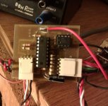
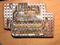
Some pictures as promised, hopefully they may be of use to some. Fitting was tight in the controller, in hindsight I should have used smaller .25w resistors and also removed the DIL sockets to lower the height. I could have reduced the strip board size a touch as well...anyhow it works, so far it seems to be quite accurate (and above all very useful ;) ) but I've not run my 10Ah Turnigy pack fully down yet. For the PD in the gauge I've ended up with 58K (62K ¦¦ 1M) / 18K for FSD on the meter.

Board:

DSCF5407.jpg


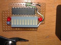
Gauge:

DSCF5400.jpg


DSCF5401.jpg


DSCF5433.jpg


Fitted to controller, picked up the +5v, VBatt and 0v from convenient points on the PCB.

DSCF5432.jpg
 
Very nice work, NRG. Mine was pretty much the same size as yours, maybe a bit shorter, but was slimmer as I didn't bother with sockets. I made a small PCB (using the 'iron-on' laser toner method) for mine, which may have saved a few mm over a stripboard layout.

Spinningmagnets, the + and - current sense wires go to either side of the existing shunt on the controller, with the + lead going to the FET side and the - side going to the battery negative side. The existing code is set for a 5 mohm shunt, but the values can be changed pretty easily to suit any other value. You could just as easily use an external shunt, it would work just as well, but would introduce a tiny bit of extra loss into the system (only a couple of watts at 20A).

Jeremy
 
Jeremy Harris said:
gwhy,

That display looks neat and has the overwhelming appeal of being much cheaper than the meter I used. The one thing to watch is that the low battery indication method I used (driving the meter into overload mode by applying more than 1V to it) may not work with the bargraph, so may need to be disabled or modified in the code. I like the idea of including the LVC warning in the meter.

Jeremy

I Have been thinking about a small mod in your code that will allow a led to be used for a LVC warning. I will have a play and report back. Basically use the calibration pulse to drive a led, Im not sure if it will fit into the 1sec time slot but it might be worth having a look. I have been playing around with the 18X as this can be overclocked 8) .
 
Should work OK, gwhy, and has the advantage of not needing another pin. I did think of using the 14M to get a few more ports, but liked the challenge of fitting this into as small a space as possible, inside the controller. I'm not sure I could have managed to squeeze the bigger chip in.

There's another way to make a low battery warning, using the "bar display with alarm flasher" circuit in the National data sheet for the 3914. I think this should work in dot mode, if the capacitor and resistor (C1 and R1 in the figure) are connected to LED 1 instead of 10. What should then happen is that the last LED will flash on and off as a warning (I think, I've not tested it). It would have the side effect of flashing the last LED when the meter is reading a low current in current mode, which may be a snag.

Jeremy
 
I have just been reading about the 08M and this can also be over clocked to 8mhz !! how cool is that..

This is my mod'ed and re-vamped display.
View attachment 1

And this is the very nearly finished ( prototype) picaxe18x pcb to drive it.. I have moved some stuff around on the pcb and have now made it even slightly smaller. The meter will monitor battery voltage ( in 4 stages ) and also has a 2 stage low capacity led ( 20% and 10%) :
bat meter.jpg
 
Jeremy or NRG,
Did you have any problems with the current amp with saturation ?. It appears that the input needs to be biased to use on a single supply rail .. I have only just noticed this when I started to do some measurement testing with it.

Edit:
Scrap that... school boy error , I had the wrong chip in the socket :oops:
 
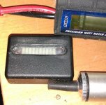
Ok, Final, Final display for my meter ....
final design.jpg
rear.jpg
new meter.jpg

Small vid of the whole meter Initialising :
[youtube]QP28RIiXjxE[/youtube]
 
Back
Top