Single Gear Stealth Build - Battery in Frame Tubes

I have one of those overprice Park nipple drivers. I usually end up using a spare spoke with a nipple reversed on it to control the depth. I use bee wax on the spoke threads to keep the nipples from becoming to difficult to true or remove in future.
 
leelorr said:
I realize that you may be tackling the "invisible battery" idea for the challenge, but I thought that the new Luna Cycle 6AH battery might also be a solution. I have seen photos where it fits completely in a small seat bag meant to hold a tire tube and patch kit.

https://electricbike-blog.com/2016/05/08/the-most-power-youll-ever-be-able-to-fit-in-your-pocket-6ah-3-3-lb-30q-luna-mighty-mini-cube-pack-reviewed/

Funny, I tried to get him to make this pack a year ago. Well, my pack was the same size, and weight, but has 50% more Amp hours. The difference? Mine is only 36v, and luna is just not too interested in that voltage. Stilll, my pack it good for 25 mils (or 50 miles a day since I charge at work). It is WONDERFUL to have a "pocket" size battery on a light bike.

I'm glad he put my idea into production (even if it isn't the voltage I would have choosen).
 
LawrenceEaden said:
Hi All.

I'm a little way into my build now and I thought I would share my experiences. My main goal for the project is to build an eBike that doesn't look like one. I recently got a single gear bike to try because i like the aesthetic and simplicity. A bike like this has a compromise with the gearing though, you can choose to make it easy to take off at the lights and get up hills, or have a good top speed.

This lead to my eBike project, could i gear the bike for a good top speed pedalling, then have electric assist for hills and getting off the line.

Lawrence, I love your work. Thanks so much for sharining.

A couple of comments:
One of our swedish friends did this a couple of years ago. very similar to what you did, with the same problems and ideas. He did several builds, take a look at them. He'll give you good inspiration!
https://endless-sphere.com/forums/viewtopic.php?f=6&t=59225
https://endless-sphere.com/forums/viewtopic.php?f=6&t=68305

I built a bike like this 3 years ago, the first single speed build on ES. If you use a freewheel version of the Q100, you can easily modify it to be 120mm. That is the size the motor was originally inteded for. And, with a singlespeed build, you don't have to dish the wheel at all - the wheel fits right in the middle of the hub.

With a small 2kg battery, it is easy to put it in a bag and make it steath, althouhg I like the ideas you have. My bike comes in at 29lbs with battery, 25mph cruising speed, and 25+ mile range. I look forward to reading more from you.
 
Awe, I'm bummed I saw your thread so late.  That freewheel Q100 works perfectly on a 120mm drop out Single speed bike like yours or mine.  Well, you'll know for your next build.  If you have any reliability problems, a spare Q100 isn't too expensive.

for a cheap leather to work with, I just went to the local salvation army.  Rather like your idea.  Beats sourcing it new!

@madrhino  " The stealth goal is not that easy to achieve, and impossible with a hub motor on a fixie that has by definition: Minimalist wheels and components."

not really impossible.  Quite easy in fact..  My "fixie" looks like a regular bike with an internally geared hub.  That is because it has an internally geared hub- it not for changing gears, but a geared Q100"  So, yeah a single speed with a Q100 is stealth because it looks just like any bike with an internally geared hub you can get from a bike shop.

Its almost impossible to tell Lawrence's bike (or mine) is powered, unless you know exactly what a Q100 looks like (vs an internaly geared hub)


@dev8h
I burned out a couple of controllers having them in my bag.  I now have it outside on my two bikes for years now with no problems.  I know, I run my controllers hard, but the really didn't like being inside (even if they are only putting out 10 amps!)

Lawrence,
I'm curious to your speed goals, what RPM motor you got, and what gearing you will be using?
 
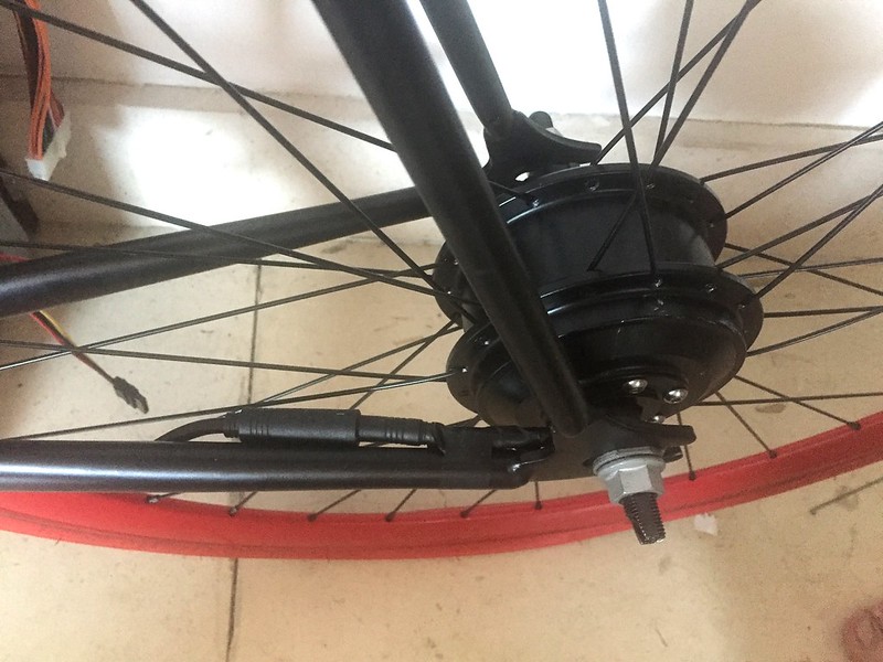
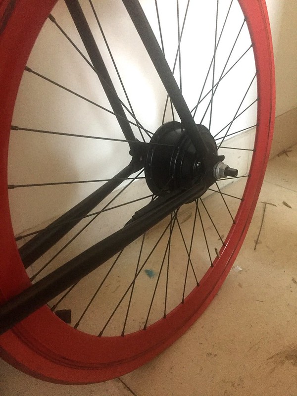
I saw some of the tools for helping with the nipples, but it didn't take long to do just the one wheel, quite relaxing. and using the nipple as the tool is free...

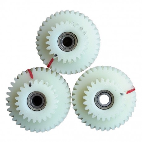
@chas58 I tried to find a freewheel q100 but I couldn't anywhere that had 32 spoke holes, the only one I found by going through this forum had 36 holes and I wanted to keep this style of rim.

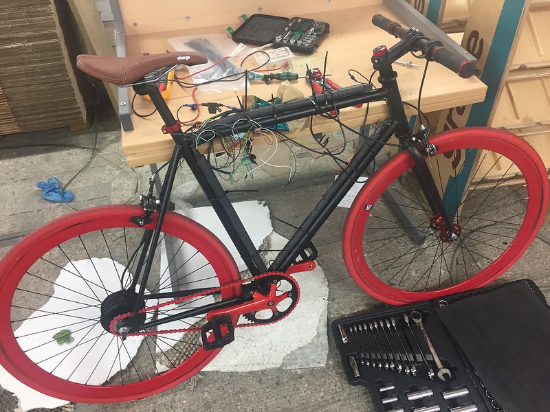
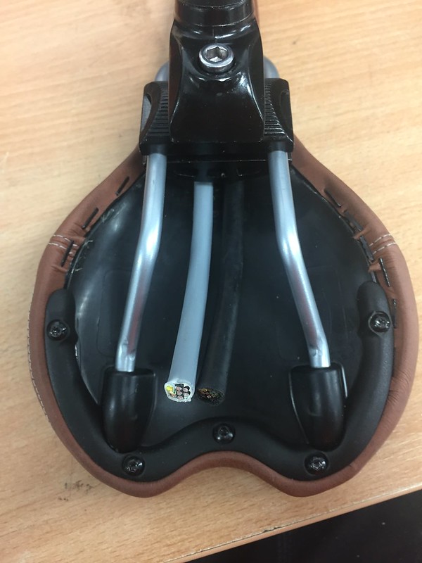
I've been looking at some of the other threads for stealth builds and I don't think I'm doing enough, I wondered if I could be rid of the frame bag completely, and the throttle. Could the only visible part of the build be the motor? I would have to displace all the components in the bag, the controller, key ignition, and battery indicator.

Redefining the Controller.

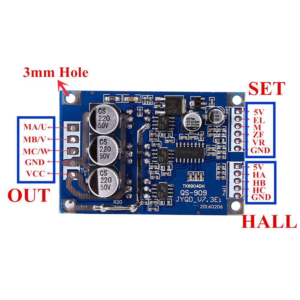
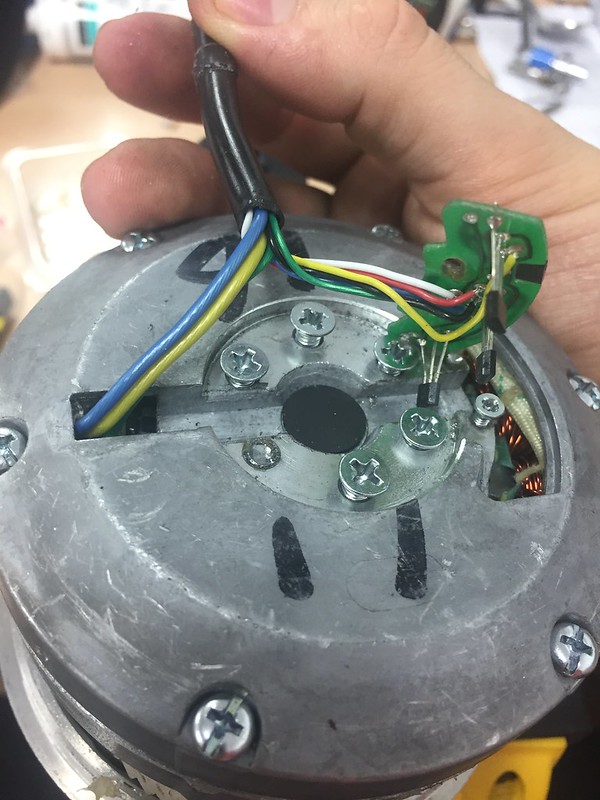
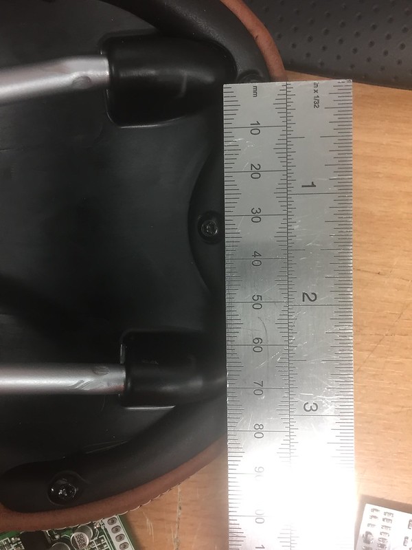
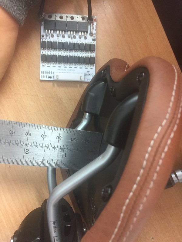
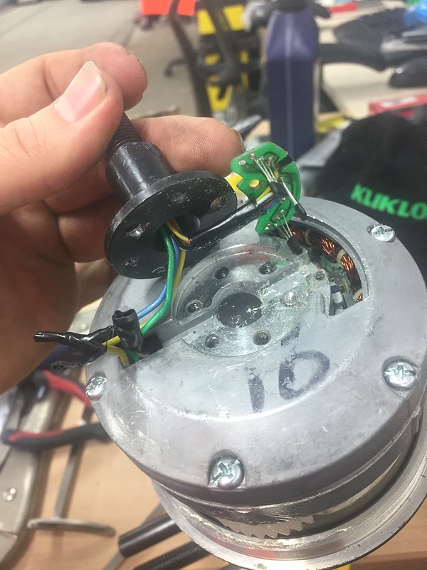
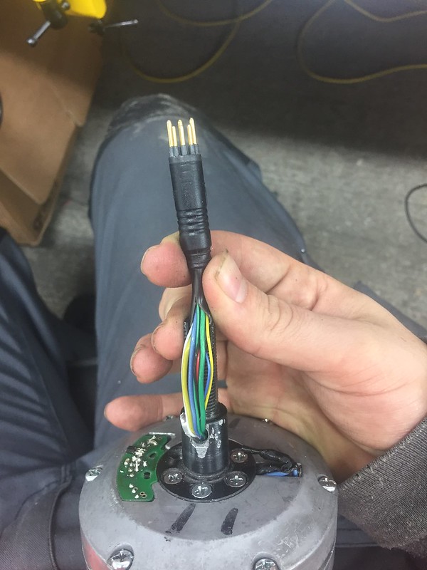
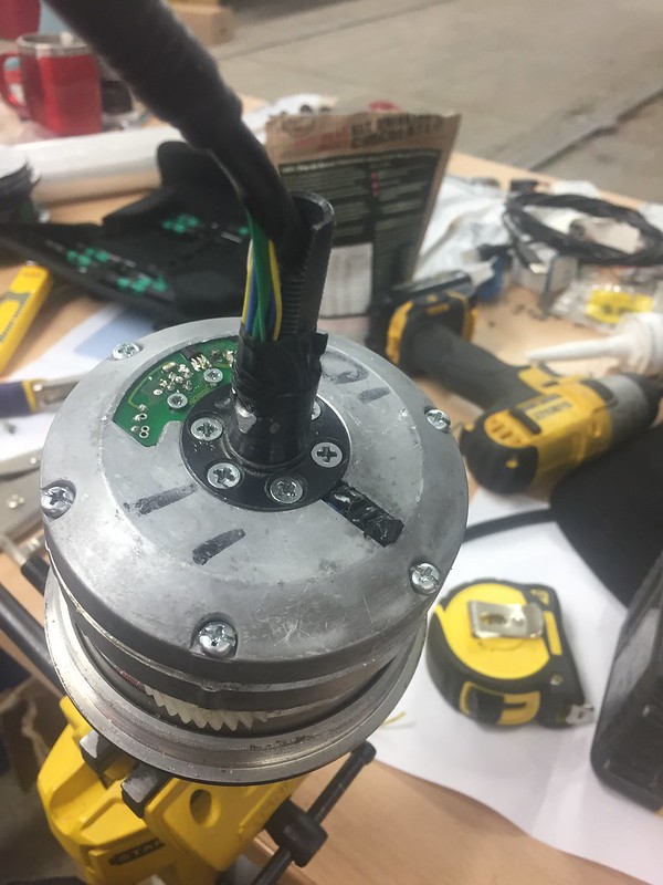
As I was reverse engineering the controller I realised how many functions on it are over spec'd and redundant on my build. If I wanted to only control the bike with a signal wire did I even need an eBike controller? I found another option on ebay that is far smaller.

s-l1600.jpg

http://www.ebay.co.uk/itm/322254223210 (£8.59)

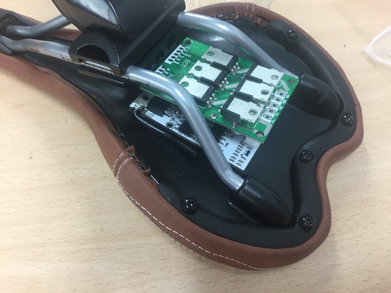
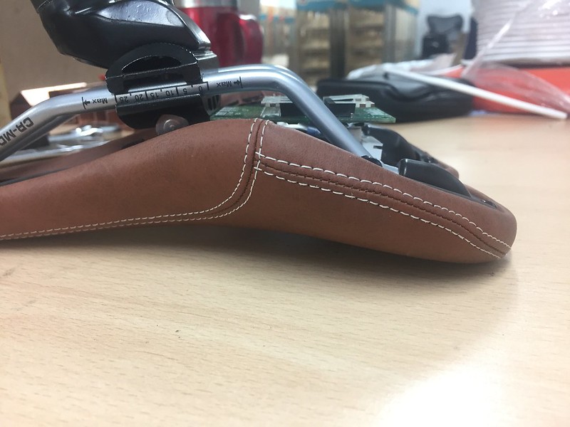
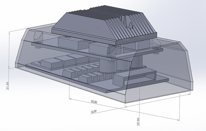
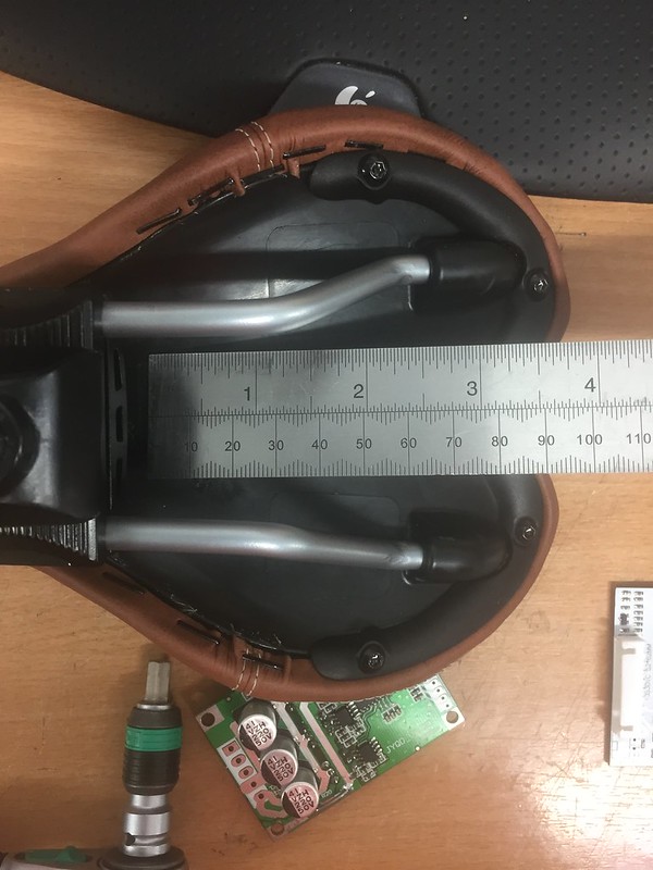
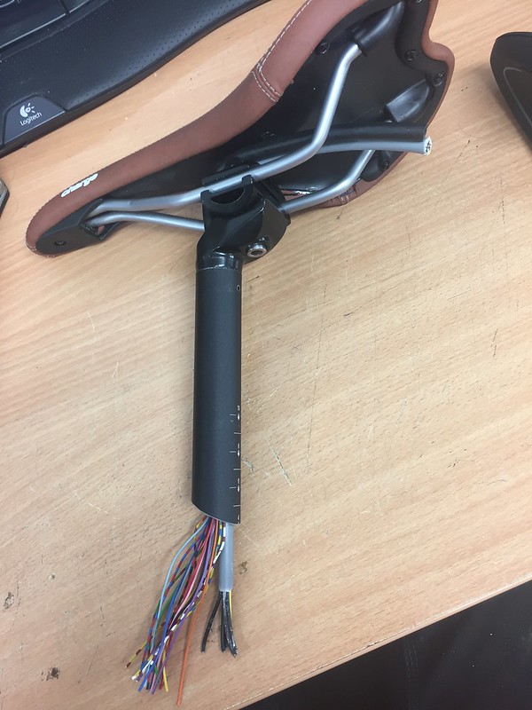
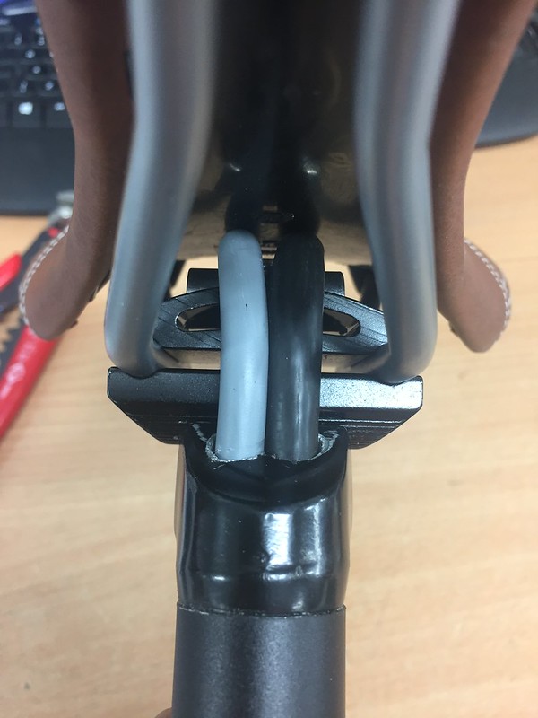
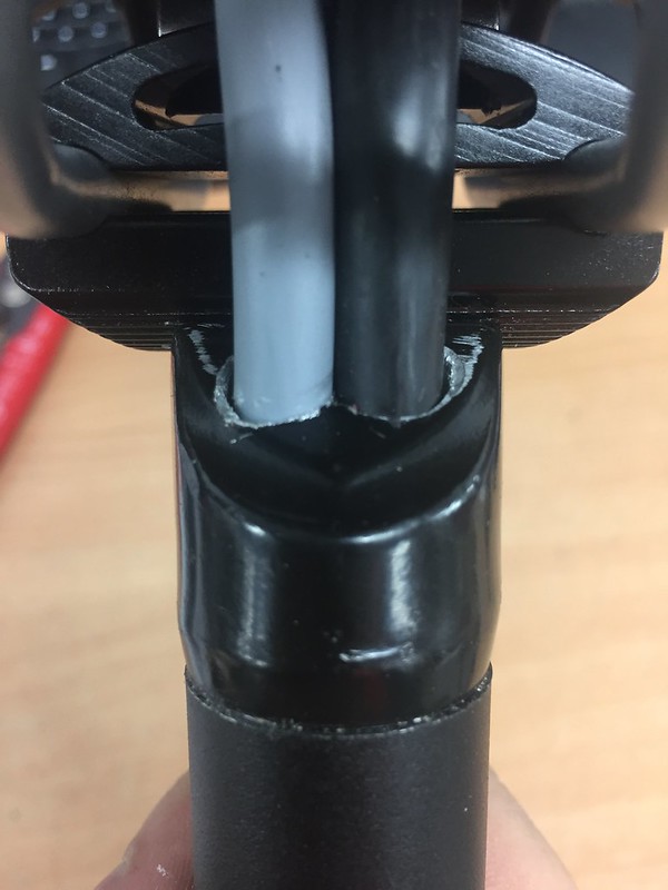
This is a simple board for controlling a BLDC motor, I am going to get one to see if I can work out which component limits it to 36v and if a fully charged battery would burn it out at above that voltage (40v). It's a step towards designing my own board to integrate bms and motor control which is the plan down the line, but even with them as separate boards I'm getting into the realms of fitting them under the saddle in a 3d printed hard case. This could be completely invisible from the side, with a rear light covering it from the back. Exciting!

Ignition Switch

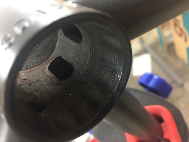
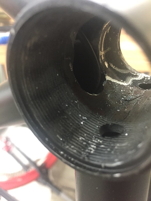
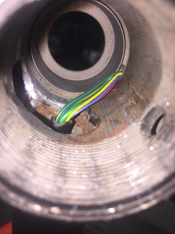
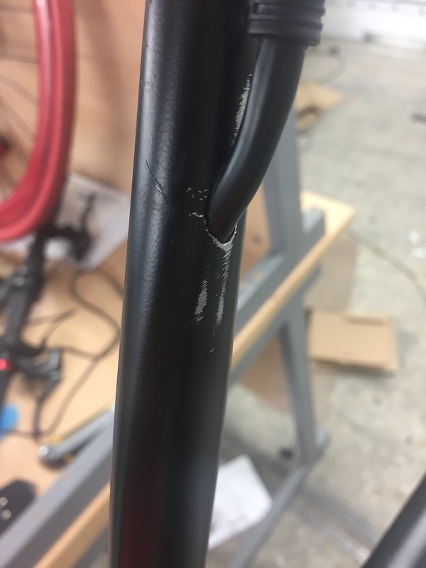
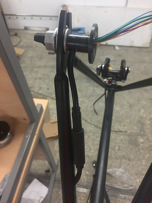
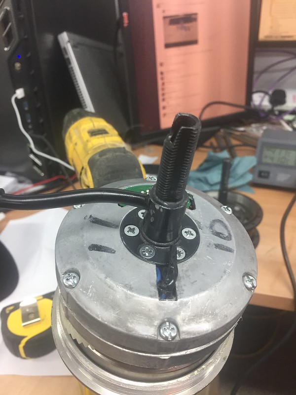
I am quite worried about security for the build as with anything you put work into. I saw on here a really cool GPS tracker that slots in the head tube (one of the few places I have left to put anything on the bike).

s-l1600.jpg

http://www.ebay.co.uk/itm/181461850317?_trksid=p2047675.m570.l5999&_trkparms=gh1g%3DI181461850317.N36.S2.R1.TR4 (£28.97)

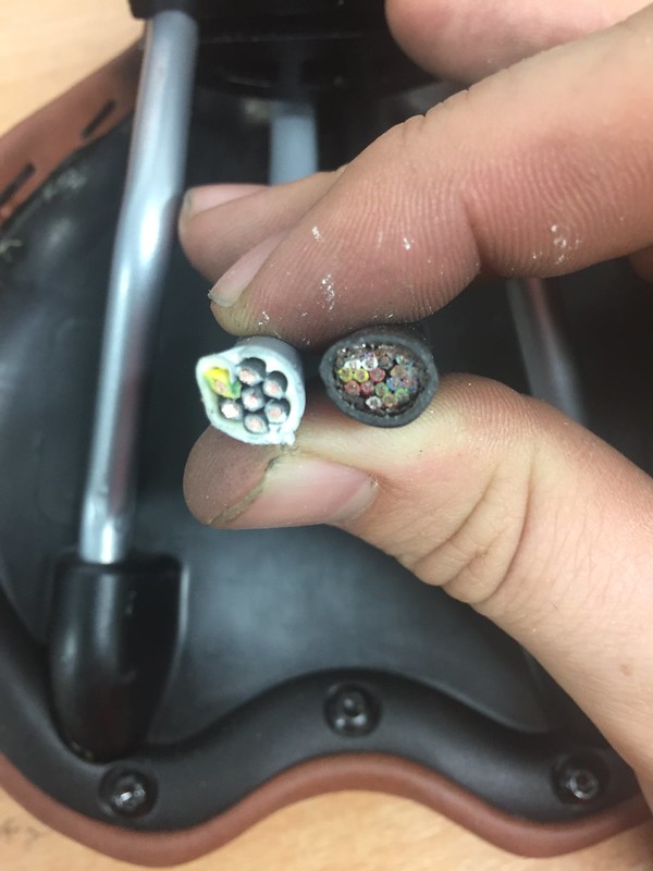
This can be armed and disarmed with an RFId tag, I'm hoping that I can find a part of this circuit that I can run a wire from out of the bottom of the fork back into the frame to my controller. This would let me switch between the gps tracker and alarm being live, or the motor being live with a quick tap. (Also super confusing for anyone trying to steal it).

Throttle

For simplification the project so far has worked around using a thumb throttle, which i think I will still use to start and get it going. I always thought that the cadence sensors wouldn't work for me because i want to use the electrical power from standstill. (I realised my build is the eBike equivilent of a koenigsegg regera in terms of power train if you count me as the ICE). I've learnt a lot about torque sensing bottom brackets and it sounds ideal, as i put all my weight on a pedal from standstill the motor will shoot me forward (hopefully).

TDCM_120.jpg

http://www.ebikes.ca/shop/ebike-parts/torque-sensors/tdcm-120.html (£118.57)

It's a bit more of an expensive option so it will probably be one of the last things on the project when I know the rest is working, but it would be the icing on the cake to have nothing extra on the handlebars. This torque sensor outputs a voltage between 2.4v and 3.4v. I would need to create a small board with some op amps to modify this to run with the other driver board if it works.

Battery Level Indicator

I can simply this to a LED bargraph somewhere on the bike, this is one thing that would be nice to have visible as I ride. Perhaps it could be recessed into the stem with a smoked polycarbonate cover, anything that doesn't look out of place when the bike is off. The control circuitry for this would be integrated in the same board I would make for the bottom bracket. I'm unsure whether to use a mirco - controller for these circuits or keep it as basic components and chips.

s-l400.jpg

http://www.ebay.co.uk/itm/10Pcs-10-Segment-Led-Bargraph-Light-Display-Red-Yellow-Green-Blue-New-K-/131982251643?hash=item1ebac1567b:g:kgYAAOSwHsRYD3Jv

I like that this one has a blue one on the end I could program to indicate charging.


This is a classic example of a project getting extended when not far from conclusion, but I think it's a good time to make the change, not too extreme and all still achievable. (lucky i hadn't cut the frame where the bag was going to go yet).

Tonight I've been truing the wheel and I'm tempted to zip tie everything to the outside of the bike and have a test ride.
 
hmm, on the german pedelecs forum I came across their homegrown equivalent of a cycle analyst. Its a bit down the track from where you are now, but the idea was to use a simple motor controller and park the 'smarts' in the 'brain' elsewhere. I.e. a higher degree of control over the controller. I thought this might be useful to you as once you want to pick and choose functionalities, no doubt you will require code to do so - theirs is freely available on the net. Food for thought anyway.
 
I like your ideas.

I too would like a good torque sensor. I think my biggest problem is that they all have an LCD unit they need to run - although I guess I could put it in a frame bag possibly. Think about what you want to do with the control window for that torque sensor. A simple controller would be great - I just use a simple throttle.

since there is no throttle for a drop bar bike, and my motor is low powered, I just use an on/off switch for my throttle (a door bell actually). I have a small button I could hide in the brake hoods too.

Battery indicators didn't work with my original battery, so I came up with a simple solution. I ran the bike until it was dead (25 miles on that battery). that was my range. If I stay within 80% of that, I know I'm safe. A simple GPS tracker tells me how much range I have left.
 
That controller is sensorless and it might have trouble with these motors, especially with their high eRPM. The main voltage limiting component (other than fets and caps) will be the LM317 which could be replaced with a TL783 (pin compatible, may or may not be a drop in replacement).
 
I think GRIN has a really small ebike specific controller. If I recall it's $300 though.
http://www.ebikes.ca/shop/ebike-parts/controllers/c-phaserunner.html
 
flangefrog said:
That controller is sensorless and it might have trouble with these motors, especially with their high eRPM. The main voltage limiting component (other than fets and caps) will be the LM317 which could be replaced with a TL783 (pin compatible, may or may not be a drop in replacement).

I've run mine sensorless, so that isn't an issue (well, its not optimum from a standing start either). The high eRPM could potentially be an issue.
 
@Lurkin I saw that a little bit. I'd prefer any control system to be arduino based if I was going into microcontrollers for the easiest integration with other systems I might add to the bike.

@chas58 Thanks. Why would it need an LCD screen? from what I read there is a signal wire which outputs between 2.4 and 3.4v dependant on crank torque. Did I get that wrong? That throttle sounds good, how do you use your throttle? Do you use it from standstill? do you feather it the whole time you're riding?

What about your battery indicators didn't work? I was going to get a driver chip for one of those LED bargraphs, then use some op amps to process the battery voltage to map 36-42v to 1-5v or similar.

@flangefrog Is it sensorless? What are the hall wires on the right hand side of the photo of the board for then? what do you mean by the term eRPM? Thanks for the tip on the LM317, i will inspect when it arrives.

Motor Burnout

So i got everything together on the outside of the bike to give it a first test ride around the factory, it was working on the stand, all good. Then as the guys were playing with it, spinning up the back wheel with it off the ground they did a kind of burn out on the floor (motor at high rpm) for about 2 seconds then after I smelt a plastic/rubber smell. It wasn't until the evening when I wanted to have a go I noticed the motor was spinning in the casing but not turning the wheel, you could get it to turn sometimes, but not others, dependant on wheel start angle.

I'm assuming this means stripped gears inside. I know the motor isn't designed for doing what it did, but i expected a little durability. I've read other cases where people have done this on here, but that's usually when overpowering the motor, and then I've been unable to find replacement gears anywhere that will fit.

The closest I've found is on BMSBattery where I got the motor originally.
a-set-of-q100-gears-ebike-kit.jpg

https://bmsbattery.com/415-large_default/a-set-of-q100-gears-ebike-kit.jpg ($8.90)

But it says it will not fit my model (Q100C CST). Does anyone have any ideas? or is this a super expensive mistake and means a new hub motor? I'll disassemble the motor this week to find out more.

30627390356_32069b2b12_c.jpg
 
That is probably your best bet for the gears (see the other thread here with the same question). They may be too wide, or have the wrong reduction ratio. Doing burnouts is a good way to break something – the frame isn’t designed for that torque either, you don’t have torque arms, so something is going to break. Be gentle with that thing

Like the charge saddle!

The torque sensors I have seen are designed to work with an LCD in order to set up all of the parameters. You could probably figure out a way to do it without the screen if you wanted to use a simple configuration?

36v 10a isn’t too powerful. I can use it at full power all the time. Generally I pedal without the motor at speeds 15mph or below, so this solution is perfect for me. Yes, I can use it from a dead stop to help accelerate.
Indicators: LiFePo4 batteries maintain a constant charge, so the indicators are worthless. I checked once when the battery was 90% dead (based on range) and the indicator said it was 80-90% full based on voltage. Constant power is one benefit of LiFePo4.
 
@chas58 I think I'm going to get another motor. I'm trying to find a Q100C without the freehub to swap the internals into my Q100C CST. This would mean I can get one with 36 spoke holes because i won't be using the shell, also I can then use a single gear freewheel instead of my chopped down hub. (cleaner). I think it's actually the clutch that has worn out in the motor, not the gears now, but I still need to investigate further.
I'm going to wait a little bit to get one of the bottom brackets to spread the cost a bit whilst I still have lots to do, good info though.
Ah, I haven't read a lot about LiFePo4. So much to learn.

Frame Modifications

Because I hadn't taken chunks out of my frame for a few days I got the die grinder out again to work out the cable routes though the bottom bracket. This is how the frame started, I've noticed in all the tube welds there is a relief hole, i'm assuming this is for air flow during welding, or to purge the inside with flux.
30653515071_a938d739e0_z.jpg

2 minutes later with a carbide bit...
30106284053_caefed57ab_c.jpg

This cut is pretty rough but it was so difficult to keep the bit from biting and it will be hidden, I just need to smooth it out so wires don't snag.

I want to try and get the motor cable to run mostly internally as well (inspired by seeing the hole in the photo above that goes to the rear drop arm).
30704340996_238936546e_c.jpg

If I strip off the outside sheath i can lay the wires flat to go around the bottom bracket without having to take any more material out. I just need to cut back about 5mm of thread off the bearing cup on the non drive side.

Motor Modifications

I never liked how the motor wire protrudes so much from the end of the axel. I've drilled a hole in the axel on the inside of the drop out, probably best I just post the photos.
30704481326_821454ed7e_c.jpg

Using the vice on the flat section of the axel to let me file the shaft and get a flat surface on the same plane as the top of the vice, making it parallel to the tangent.
30704402696_3fb71cd124_c.jpg

A bit of fiddling with a drill, file and die grinder later..
30440574410_e02ab91d8a_c.jpg

Wires in the motor at a good point to cut and splice together once shortered and I'm 100% sure the lengths are all right.
30440632440_917a942d77_c.jpg

30108977804_1198a0d3da_c.jpg

a bit of black on the filing marks and hopefully it will be completely hidden.
30652935641_b604f27415_c.jpg

Rough positioning of the 'Juliet' connector. Fixing method to be determined, probably make a brake line style crescent profile slot to braze on.

Controller Packaging
My new driver board for the motor has arrived. I'm hoping to fit it, the bms, and a little extra board I'll have to make up for throttle/torque sensor signal processing. I'm going to design a hard case to be 3d printed that can clip onto the metal bars of the saddle from the inside, this should let me swap it between saddles if I want because the dims of these are universal.
30624440692_5f83664573_c.jpg

30652868891_df922a7f00_c.jpg


Next Steps

-Finish off the batteries and fit connectors to all ends to make it easy to slot in/out.
-work out what i'm going to do about my knackered motor, find the root cause of the problem.
-Controller hardcase design
-Signal processing design
 
LawrenceEaden said:
I never liked how the motor wire protrudes so much from the end of the axel.
Agreed. That is one reason I am running a Bafang hub motor rather than a Cute. That side of the hub is fixed to the axle. Why did you not simply bring the cable out a hole in the side of the hub?
Edit: never mind that question. I see that there is a cover that goes over it :(
Reference: https://endless-sphere.com/forums/viewtopic.php?f=2&t=61966

LawrenceEaden said:
I'm going to design a hard case to be 3d printed that can clip onto the metal bars of the saddle from the inside, this should let me swap it between saddles if I want because the dims of these are universal.
They are not as 'universal' as one might hope. Most often it is simply the height/angle of the front or rear mounting but more extreme cases can be found. Recently I had to use a bench vice to permanent bend the bars on a new, off-brand (sarcasm) Schwinn saddle such that they would fit the standard seat clamp on a Thudbuster seat-post. A saddle with springs changes many things as well.

The idea of designing your controller case to mount across the seat bars behind the seat clamp is excellent. Might I suggest looking at some of the Rock Brothers Saddle bags 'clamps' for ideas.Rock Brothers X.jpg Reference:
http://www.ebay.com/itm/252033393110 http://www.ebay.com/itm/141754825225
 
@Mündawg Thanks!

@Motomech Ah, I just saw the bafang motors that do that. The shaft that I have drilled is the only external non rotating part. If you see the photos the next part has the screws for the brake rotor on.
Good to know about the saddles, I'm designing it bespoke for my charge saddle so I'd prefer not to compromise to make it universal.

Saddle Bag

This is a quick mock up I've made of the hard case to go under the saddle. Dims in mm. (it's upside down, the heat sync would be the only bit visible from the side of the saddle).
30643198232_6f722b7540_c.jpg

A few photos showing rough dimensions of the saddle.
30759886925_f04c0095bf_c.jpg

30643343402_f2f435a943_c.jpg

30759887175_6d16ddd9ca_c.jpg


Pretty tight packaging, but i'm sure with some good contact area to the heat sync it should stay cool, if not i'll know about it pretty quick through the saddle.
 
LawrenceEaden said:
@Mündawg Thanks!

@Motomech Ah, I just saw the bafang motors that do that. The shaft that I have drilled is the only external non rotating part. If you see the photos the next part has the screws for the brake rotor on.
Good to know about the saddles, I'm designing it bespoke for my charge saddle so I'd prefer not to compromise to make it universal

I don't think you meant me as I didn't make a comment.

But while I'm here;
The Q100 uses a Spragg clutch that is pretty much bullet-proof, so I don't think it is the problem. Besides, even if it was damaged, it wouldn't put off a smell.
Those gears listed on BMS B. only fit the standard(not "H")328 version of the Q100. no good to you.
Since the wheel is laced, I would buy another Q100C 201 and not let idiots do burn-outs with it.
Why the "C" over the "H"?
Well yesterday, I rode my Q100C bike in the afternoon and my 2WD(W/ a 260H motor on the frt.)and was struck how much quieter the "C" was. On the same packs(12S) and controllers(Elifebike 9-FET, 17A), the "C" is dead silent, while the "H" had a deffinate growl to it. By way of comparision, my larger Ezee geared rear fall in between the two Cutes.
 
If the bottom (or top depending on orientation) of the heat sink could be extended outward such that it clamps on to the seat bars then that would add a much deeper heat well....just a thought.
 
If you build a rear light into the back side of this saddle, even a close inspection will just look like its a safety rear light.
 
@motomech. Ah I think i got a little confused. That's good to know between the C and the H. My only reasoning for the H is that it has a threat to put a single gear freewheel on instead of using my modified on for a cleaner look, I'll stick with the C then.

@lewtwo, it's not the easiest thing to reverse engineer, I think there was a lot of tolerance in the bar bends when it was made, they're not perfectly parallel. Perhaps if this isn't sufficient.

@MrDude_1 I've been thinking about this! It was between that or adding a little clip on the back to easily put a light on, i could copy the profile from another light.

Frame Modifications

I think I may have finished hacking up my frame now, I made the cut in the lower rear arm for the motor cable.

30760398751_1bc7f66cec_c.jpg

30731639202_44e114e502_c.jpg

30760397461_094c13cee8_c.jpg
 
Seatpost Modification

I've drilled the seatpost for the cable routing between the saddle case and the frame. I've found there is nearly no room at all in the frame at the seatpost for connectors, especially since 21 wires have to be connected there. I think this means I'm going to have to solder, more annoying to disassemble if something breaks, but it looks like the only way. These are just some cables I found spare at work with no specs on, the 20 core looks good for the balancing and communication wires. The 6 core I'm not sure is thick enough for the battery and motor wires (and it's grey), so I'll replace it with one I know can hack it.

30919688645_5e59d59a28_c.jpg

30618674860_ec115864cc_c.jpg

30803646422_d4e845c1ab_c.jpg

30285398484_7088391d93_c.jpg

30883777086_bba319f5ac_c.jpg
 
It's been a little while since I've worked on the bike properly, I've been modelling up some of the components and modifications for a full 3d model at the end.

Motor Modification

I cut the motor wire and soldered up all the connections.
31175536505_69210fcfc0_c.jpg

To get the bearing to slot over the shaft and the wire I had to remove a little material and strip the outer sheathing from the wire so it could lay flat.
30368353003_75737a5c1d_c.jpg

30354334504_3e7ee1a61a_c.jpg

30354334524_ef15309d2c_c.jpg


And it's done.
31216741101_0db0171a96_c.jpg

31187805402_201db75968_c.jpg


Battery Upgrade

I stumbled across a deal on 18650s on gearbest for NCR18650B cells.
BatterieLi-ionNCR18650B-525x340.jpg

http://www.gearbest.com/batteries/pp_383600.html?wid=21

At £3.10 a cell to upgrade my pack to 245wh I thought it was worth the investment. This will bring the range up to the same as some retail ebikes, but still hidden! I'll keep using my current pack for testing and early use. I can always appropriate my these cells later to a range extender pack.

Another advantage is these cells have a slightly higher current draw with 2C being 6.2A upping my packs output to 12.4A, It could make all the difference.

Connector Rethink

I found when test fitting all the components that there is no room in the frame for any connectors and I might have to solder the connections. Then i remembered I have loads of jumper cables with the little male and female connections on the end. Perhaps these could work for the signal and balancing wires. I could connect them up with some heat shrink over which could keep enough compression for a reliable connection. This would help out a lot where I have to make approx 16 low power connections in the seat tube.
F7916454-01.jpg
 
Back
Top