
Voltage sag looks pretty minimal for that current. How was the battery temp?
You are using an out of date browser. It may not display this or other websites correctly.
You should upgrade or use an alternative browser.
You should upgrade or use an alternative browser.
Solderless A123 pack
- Thread starter nuxland
- Start date
4 of the sensors are attached to the cells and two of them to minus and plus busbars.fechter said:Voltage sag looks pretty minimal for that current. How was the battery temp?

And I also used 20cm diameter big fan to blow air when charging in the car.
But it seems it only affected this end where I was blowing air
")
Attachments
Geez, barely warm. Pretty impressive.
With a typical axial fan, you can't get much air flow through a tight space. If you use a centrifugal blower, you can get way more air to go through a small opening.
With a typical axial fan, you can't get much air flow through a tight space. If you use a centrifugal blower, you can get way more air to go through a small opening.
Installed forced air cooling to the pack, to keep cells cool and also cool them during charging.
Are using two radial fan, each outputing 61 m³/h. And it seems they can push air through between cells

And here is little video how much air is coming through. By the feel it should be enough to cool it.
https://youtu.be/DEs1BF7K_WE
Are using two radial fan, each outputing 61 m³/h. And it seems they can push air through between cells
And here is little video how much air is coming through. By the feel it should be enough to cool it.
https://youtu.be/DEs1BF7K_WE
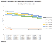
Tested Aircooling and it works kind off
It can cool down the pack in 60 minutes to ambient temperature.
But still temps went as high as 57C in second race with that pack.
The track was also very accleration and braking intensive, so my rear brake disk overheated also
Temp 1 and 6 are output wires and aircooling does not reach them.
Temp 2 and 3 are fifth row from front in first and second level and they cool good.
Temp 4 and 5 are fourt row from back in first and second level and they cool slowly.
View attachment 1
nuxland said:Want to build solderless pack and need some opinions.
Basically ANR26650M1 cells are sitting inside orange enclosures 10 in parallel.
Together the pack will be 32s10p.
Connections will be made with 0,5mm thick copper like in this image but 10 in parallel Battery.jpg.
There will be rubber rings in each cell top and plexiglass on top. Then everything is bolted together with m4 long thread in each battery.
Attached is also how the turn will be when two packs are sitting in top of each other.
Also final size of 34s9p (will change this to 34s10p instead), together 23Ah but capable around 60kw bursts. Weight with bms and everything should be around 32kg.
34s9p.jpg
I already made a sample copper and using 3d printed tool to deepen it. Made a measurement error and copper is a little bit short
ToolAndSample.JPG
Question is: are these connections capable of 600A in burst and 300A continious? 0,5mm thick copper and 1cm wide for each cell should do 0,5mm2 and 10 of these should do 50mm2.
Also copper is pressed against battery with enough force (rubber ring between copper and plexiglass), so that should be enough, as right now I'm using 35mm2 wire in my kart and thats ok.
Hey Nuxland
Do you have stp.file for these copper connections?
Best Regards
Pota
Hey
Only dwg is and pdf.
But in this dwg lenght is 1mm short. I had to file bigger both side two holes so that copper will fit to holders.
Reason is that when I stamped copper it shrinked and I calculated it 1mm wrong for the whole lenght
Only dwg is and pdf.
But in this dwg lenght is 1mm short. I had to file bigger both side two holes so that copper will fit to holders.
Reason is that when I stamped copper it shrinked and I calculated it 1mm wrong for the whole lenght
Attachments
yes it was 0,5mm thick.Pota said:So what is the correct length, width and thickness of each module? Wasent it 0.5mm thick?
Im building the same pack. Just as 6x 6s10 packs
I calculated that it will shrink 3mm but in reality it shrank 4mm.
So my drawings are 1mm off in length I think.
We never bothered to correct the drawings afterwards, because will not produce these again
You have to measure your cell holders and then draw. Just remember that in my case copper shrank 4mm when I punched these pumps in copper.
Pota said:What did you use to press the copper to the battery? plastic O-Ring and paste?
Actually ended up not using any paste.
I used 8mm thick foam (you can see that in some of the pictures) that I punched out of bigger piece. I pressed it down to 2mm.
rojitor
100 kW
I LOVE this thread. Amazing job.
nuxland said:Want to build solderless pack and need some opinions.
Basically ANR26650M1 cells are sitting inside orange enclosures 10 in parallel.
Together the pack will be 32s10p.
Connections will be made with 0,5mm thick copper like in this image but 10 in parallel Battery.jpg.
There will be rubber rings in each cell top and plexiglass on top. Then everything is bolted together with m4 long thread in each battery.
Attached is also how the turn will be when two packs are sitting in top of each other.
Also final size of 34s9p (will change this to 34s10p instead), together 23Ah but capable around 60kw bursts. Weight with bms and everything should be around 32kg.
34s9p.jpg
I already made a sample copper and using 3d printed tool to deepen it. Made a measurement error and copper is a little bit short
ToolAndSample.JPG
Question is: are these connections capable of 600A in burst and 300A continious? 0,5mm thick copper and 1cm wide for each cell should do 0,5mm2 and 10 of these should do 50mm2.
Also copper is pressed against battery with enough force (rubber ring between copper and plexiglass), so that should be enough, as right now I'm using 35mm2 wire in my kart and thats ok.
https://www.alibaba.com/product-detail/battery-holder-for-26650-cell_60584266707.html?spm=a2700.8443308.0.0.1b513e5fFcoeYv
These are 0.8mm wide.
I got copper 0.6mm thick, that would equal 48mm2 correct?
You only have one layer copper?
Matador
100 kW
- Joined
- Jun 29, 2016
- Messages
- 1,045
So 34S10P of ANR26500 nano LiFePO4 (112.2V nominal, 25Ah, max 500A continuous or 1200 A burst 10 sec, aka 56kW continuous or 135 kW burst 10 sec)... each cell rated 2500 mAh, 50A continuous (120A 10sec burst) with 6 milliohm AC impedance (ACIR) at 1kHz.
From your graph https://endless-sphere.com/forums/viewtopic.php?f=14&t=85912#p1297586, for around 20 volts (from 112 to 92V) of sag you get around 580 amps).
So thats R = dV/I = 20/580 = 34.5 milliohm DCIR for the whole pack (including all metal connections).
But 34S, so each 10P row is 1.014 milliohm DCIR
That's about 10.14 milliohm DCIR per cell (or even less when you substract all the copper connections) ! That's crazy!!!!!
I have sony VTC4 cells 18650 NMCs.... They give 2100-2200 mAh, max 30A, 12 mOhm ACIR @1kHz and around 22 mOhm DCIR at 50%SOC.
Similar threads
- Replies
- 2
- Views
- 225
- Replies
- 7
- Views
- 764
- Replies
- 10
- Views
- 1,026
- Replies
- 11
- Views
- 548