This shows that there is a fault in your battery. The crlls eill be unbalanced for ehatever reason. You might be able to balance it manually if there's no bad cells. You have to open it to measure the cell voltages. That will trll you what you have to do.gameofbikes said:Just measured again after 4 more hours of charging (even though according to the charger, the battery is fully charged), the battery is still 48.6V. The output of the charger is 54.6V. I wrote 53.4V above as the spec for the charger's output but that was a typo, the charger says 54.6V -- matching what I measured with the multi-meter.
I will probably be opening up the battery later today, the side where the wires are coming out from first. I'm assuming that's where the BMS also is? And when I want to eventually put it back together, what can i use to replace the thick blue plastic shrink wrap?
You are using an out of date browser. It may not display this or other websites correctly.
You should upgrade or use an alternative browser.
You should upgrade or use an alternative browser.
Think I messed up my battery or motor, help needed
- Thread starter gameofbikes
- Start date
gameofbikes
1 W
Thanks, d3veh. Is it also possible that rather than cells being unbalanced, a component is damaged, such as the BMS, or some piece of circuitry?
Or does my 48.6V measurement act as a strong clue that the cells are unbalanced? If so, how? I'm curious to know why unbalanced cells would lead to the behavior I'm seeing.
Or does my 48.6V measurement act as a strong clue that the cells are unbalanced? If so, how? I'm curious to know why unbalanced cells would lead to the behavior I'm seeing.
gameofbikes
1 W
OK, here are the pics, I'll probably need more. There is a metal plate that can be unscrewed. Wanted to post initial opening up and see if there is anything I should avoid touching, and ask if someone can annotate some of the pictures with instructions on what the different parts are, if I should remove the metal plate, and what measurements I should take now. Appreciate any advice on if there is anything I should specifically avoid doing or touching to prevent damage or injury too!
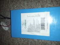
battery label with specs:
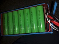
top section, showing 18650 cells:
top view of BMS:
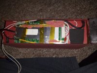
BMS view #2, showing part number?:
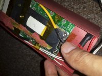
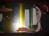
other end of the BMS, with a bunch of wires hooked up:
battery label with specs:

top section, showing 18650 cells:

top view of BMS:

BMS view #2, showing part number?:

other end of the BMS, with a bunch of wires hooked up:

dnmun
1 PW
put it on the charger and measure the voltage on each cell at the sense wire plug where it is soldered into the pcb. use the 20V DC scale and measure while charging.
gameofbikes
1 W
dnmun said:put it on the charger and measure the voltage on each cell at the sense wire plug where it is soldered into the pcb. use the 20V DC scale and measure while charging.
How do I do that? Are the sense wire plugs the solder points in the 4th image, that are labelled B0 - B14 (15 total)? Would I put the red probe of the MM onto each one of those? And where would I put the black probe during each of those measurements?
gameofbikes
1 W
Oh, and is there any way to tell from the pics I posted if there is a balancing network present? What would I need to provide you to make that determination?
dnmun
1 PW
you do not need to prove it has no balancing network because it appears that it does.
for us to help you fix your battery we need for you to measure the cell voltages as it reaches full charge and the green light comes on the charger. you can measure the voltages right there where the sense wire plug is soldered to the pcb.
for us to help you fix your battery we need for you to measure the cell voltages as it reaches full charge and the green light comes on the charger. you can measure the voltages right there where the sense wire plug is soldered to the pcb.
gameofbikes
1 W
dnmun said:you do not need to prove it has no balancing network because it appears that it does.
for us to help you fix your battery we need for you to measure the cell voltages as it reaches full charge and the green light comes on the charger. you can measure the voltages right there where the sense wire plug is soldered to the pcb.
Got it -- I should measure while the battery is switched on and connected to the charger. However, I'm not familiar with some of the terms you're using so I'm not sure how to proceed. Which is the "sense wire plug"?
EDIT: To be clear, i know next to nothing about batteries and electronics. I really appreciate that you all are helping me with this. Any instructions have to be really detailed for me to be able to follow. My understanding of electricity is nothing beyond "series means add voltage, and parallel means add current".
dnmun
1 PW
that white plug on the end has wires running out to each of the serial connections in the battery.
you measure the cell voltage between two adjacent pins.
the bottom of #1 cell is the first wire, black. wire 2, the first white wire, is the top of #1 and the bottom of #2...
just stick the voltmeter probes in the holes on the pcb next to where the sense wire plug is soldered.
your charger should be green and the DVM should be on the 20V DC scale.
gameofbikes
1 W
dnmun said:that white plug on the end has wires running out to each of the serial connections in the battery.
you measure the cell voltage between two adjacent pins.
the bottom of #1 cell is the first wire, black. wire 2, the first white wire, is the top of #1 and the bottom of #2...
just stick the voltmeter probes in the holes on the pcb next to where the sense wire plug is soldered.
your charger should be green and the DVM should be on the 20V DC scale.
It makes perfect sense now, thanks for the explanation, dnmun! 13S7P -- means 14 terminals total at the ends of the 13 series. Those are the 14 solder points labelled B0 - B14 in the 4th picture. And I guess the white thing in that pic is the sense wire plug. So I just need to measure voltage from B0 to B1, then B1 to B2, etc, while the battery is charging (I don't understand yet why it has to be done while charging, but I'm sure that will be explained to me soon enough).
I'll do this in the morning (getting late here) and post results.
dnmun
1 PW
you do it while charging to see if the cells are pushed to HVC and shutting off the charge or if something else is stopping it from charging. like an open fuse.
Be careful not to short your probes when you do those measurements. I normally put my black probe on the pad where the thick black wire is joined to the point B- and then probe each point B1 to B13, then do a bit of math (subtraction). You have to use a higher scale on your voltmeter, so not quite as accurate, but close enough to see the problem. I do it that way because one time I accidentally shorted two pins, which immediately burnt a trace on the PCB, which was difficult to repair.
999zip999
100 TW
I put shrink wrap or tape so just the tip shows, as it would be harder to short. I brace my hand to be steady so no free hand in the air. It's hot in there so be careful. Please post like.
1. 3.60
2. 2.88
3. 3.44v
13. Xxx volt
1. 3.60
2. 2.88
3. 3.44v
13. Xxx volt
999zip999
100 TW
On subject Dnmun please post pic of bms without balance circuit here to end debate.
Hope this is ok gameofbikes.
Hope this is ok gameofbikes.
friendly1uk
1 MW
Your meter looks nice, but the probes have half inch of exposed metal. It is very easy for a probe to slip off an item being tested while your trying to hold two of them and look at the reading on the meter. Often, a bit of grease or oil or protective substance sit's invisibly on the surface your probing. Your there looking at the meters unsteady reading, having to jab the probes in harder and wiggle, Watching to see if the reading settles. Risky business with ribbon cable spacing. Even resting your hand to give the precision of a pencil, them connections are still a probes width apart if you slip badly. Your probe can span half inch. Sending molten metal flying.
What you should do is tape up the exposed prongs except for the tinyest bit at the pointy end. Just leaving enough exposed to be able to make a connection, but not enough to touch two at once. With your probes taped, you might find it impossible to short a cell. Making the job quite pleasant, rather than death defying.
Eye protection is well worth a thought. The black will come off your hand over time. The carpet can be extinguished. Your eyes are not worth the risk. You need them to put the carpet out.
p.s I think I took an hour to write this :?
gameofbikes
1 W
d8veh said:Be careful not to short your probes when you do those measurements. I normally put my black probe on the pad where the thick black wire is joined to the point B- and then probe each point B1 to B13, then do a bit of math (subtraction). You have to use a higher scale on your voltmeter, so not quite as accurate, but close enough to see the problem. I do it that way because one time I accidentally shorted two pins, which immediately burnt a trace on the PCB, which was difficult to repair.
OK, so the "B-" marking on the PCB is right in between two solder points, I'm interested in the one that the thick black wire is soldered to right? I'll put the black probe from my multi-meter there, and the red probe at the B0 - B14 points. I understand that using this method the voltage will be cumulative, so i have to subtract to find the voltage across each adjacent point.
One thing I don't understand, is why there are 15 solder points there (B0 - B14). DO I measure all 15 -- black probe on B-, and then 15 separate measurements, with red probe on B0 - B14?
If I put 13 batteries in series, there are 14 terminals, so what is the 15th one? Is there one of them I shouldn't try to measure?
gameofbikes
1 W
friendly1uk said:Your meter looks nice, but the probes have half inch of exposed metal. It is very easy for a probe to slip off an item being tested while your trying to hold two of them and look at the reading on the meter. Often, a bit of grease or oil or protective substance sit's invisibly on the surface your probing. Your there looking at the meters unsteady reading, having to jab the probes in harder and wiggle, Watching to see if the reading settles. Risky business with ribbon cable spacing. Even resting your hand to give the precision of a pencil, them connections are still a probes width apart if you slip badly. Your probe can span half inch. Sending molten metal flying.
What you should do is tape up the exposed prongs except for the tinyest bit at the pointy end. Just leaving enough exposed to be able to make a connection, but not enough to touch two at once. With your probes taped, you might find it impossible to short a cell. Making the job quite pleasant, rather than death defying.
Eye protection is well worth a thought. The black will come off your hand over time. The carpet can be extinguished. Your eyes are not worth the risk. You need them to put the carpet out.
p.s I think I took an hour to write this :?
Thank you, I really appreciate this, and any other safety tips. I will tape up the probes so only enough metal necessary to do the measurements is exposed.
dnmun
1 PW
it's not that hard. just stick the point into the solder and it will stick. it won't move. that is why they put the sharp points on the probes. so they stick in the solder. just pay attention. you should do that anyway when working on electrically active devices of all forms.
gameofbikes
1 W
One thing I don't understand, is why there are 15 solder points there (B0 - B14). DO I measure all 15 -- black probe on B-, and then 15 separate measurements, with red probe on B0 - B14?
Just waiting on the answer to this before I continue with measurements.
Just waiting on the answer to this before I continue with measurements.
B0 is ground, the same as B-. You'll find it much safer and easier to do it the way I described. That's right, black probe on thick black wire (B-) and red probe on each B1 to B13. That gives the cumulative result. Peole on here don't want to do the sums for you, so do the calculation and post the actual cell voltages here.
gameofbikes
1 W
d8veh said:B0 is ground, the same as B-. You'll find it much safer and easier to do it the way I described. That's right, black probe on thick black wire (B-) and red probe on each B1 to B13. That gives the cumulative result. Peole on here don't want to do the sums for you, so do the calculation and post the actual cell voltages here.
Perfect,t hanks for the info. I don't expect people do do simple addition for me, i can handle that.
gameofbikes
1 W
Here are the measurements, of voltage from (B-) to B1-B14:
V (from B-)
B0 (not taken, because I was told B- and B0 are the same voltage)
B1 4.17
B2 8.35
B3 12.53
B4 16.71
B5 20.8
B6 20.8
B7 25
B8 29.2
B9 33.3
B10 37.5
B11 41.7
B12 45.9
B13 50
B14 54.2
And here are the calculated voltages differentials of each terminal from the adjacent/previous terminal (B2-B1, B3-B2, etc):
B1 4.17
B2 4.18
B3 4.18
B4 4.18
B5 4.09
B6 0
B7 4.2
B8 4.2
B9 4.1
B10 4.2
B11 4.2
B12 4.2
B13 4.1
B14 4.2
Why are B5 and B6 measurements the same? Is that bad? I took each measurement twice, and got the same readings both times.
I'll go to sleep and check back again tomorrow to see what this all means and what I should do next.
BTW, i'm still not sure why there are "extra" terminals. B0 - B14 = 15 terminals. But if I lined up 13 batteries in series. there should be 14 terminals (12 in between batteries, and the (-) terminal of the first battery and (+) term of the last one). But there are 15 total on this sense wire plug. Why?
wesnewell
100 GW
WAG. Either B5 or B6 circuit is bad and they strapped them together to bypass the bad circuit. Trace each of those sense wires. One should not go anywhere, or go to the same place as the other. This seems really strange to me. If you can't figure out what they have done, you should contact Calibike.
friendly1uk
1 MW
dnmun said:it's not that hard. just stick the point into the solder and it will stick. it won't move. that is why they put the sharp points on the probes. so they stick in the solder. just pay attention. you should do that anyway when working on electrically active devices of all forms.
No, the sharp points are to jab people that don't use adequate shrouding. As specified in many testing standards. I still have marks to prove it.
We have 13 voltages. One of which is repeated around cell 6, giving 14 readings
If it's a 48v battery, you have 13 cell-groups, so one pin is not used for sensing. I don't know why they've doubled up those two, but it shouldn't be important. I've seen it done on other BMSs. There's no sense wire in that pin either, so it's not connected to the cell-pack.
You have your cell voltages now and they show that everything is normal - a little out of balance, but that should sort itself out once you start using it.
You can now test to see if the BMS is switched on. Put your black probe on B- and your red probe on B14, which should give 54.2v. Now move your black probe to the point on the pcb where the thick black wire comes out of the BMS and goes to the output connector. It should be marked P-. If you get 0v or something less than 54v, the BMS is switched off. If so, try unplugging the mulipin connector and then re-plugging it to see if it switches back on. If you get the 54v, there's nothing wrong with the cells or BMS, so you have to follow the power wires to find the problem.
Similar threads
- Replies
- 5
- Views
- 1,404
- Replies
- 2
- Views
- 678
- Replies
- 20
- Views
- 1,088
- Replies
- 5
- Views
- 751

