Thuds 1st build

Regarding the Evo 2 speed transmissions:

Looks like smallest gear is 21t and runs an OptiBelt OMEGA 295 5m Timing Belt assuming RC motor driving -
7000 rpm nominal power limit @ 971w
9000 rpm nominal power limit @ 1050w

Max RPM @ 14K at 1354w nominal handling.

I think it's touch and go... just basing on the only parts we can really see, the belts I would guesstimate you could exceed the nominal by 2x and still be safe (someone who knows more about belts, please correct me if I am wrong) if properly tensioned with enough tooth coverage. So perhaps 7000 rpm @ 1800w, I wouldn't want to hit it too hard and can't tell the bearings quality or hardness of shafts and such.

As with everything I could and likely am wrong, the specs for these belts are available: http://www.bengtssons-maskin.se/uploads/manualer270.pdf

Hope this helps

-Mike
 
Thanks for all the kind words guys.

How about for future referance.

HLRS 1.0
(high/low range,selectable)

(I don't care if my name is on it, you all know where it came from)
I wouldn't have built it but for a bit of motivation from Miles. Garry's direct drive to the 3 speed hub had me giving up a high/low speed drive applicable to bicycles. I have a shimano hub I need to mod & lace up for a bike I think my wife will use.
 
Um... thud, you do realize your calling the drive the "Hillarious 1.0"? -

Actually that's pretty cool (if you are smart enought to get it right away, or take a moment to think about it - like I had to).

Transportation
Hub motor
Urban
Destroyer

Ok, that sucks... = (-

-Mike
 
Thuds Ingenious Two Speed

This obviously makes for the best acronym. :lol: because it is (acronym)

unlike Toyota's TRD ...... hmmm.... let me go buy a TuRD.

what marketing genius thought of that one .....

:?: :!: :wink:
 
My man,

The Skate Park is where that needs to go next. I saw these kids jumping or sometimes attempting to jump 50 gallon drums stood upright, but they could only occasionally get the speed to clear them. But with your setup well I'm thinking backflip. :twisted:
 
I think i owe a video yet & I will be losing the weather very soon(more so now than the crappy summer we had)
Tonight I motivated to adapt my e-bay 219 sprocket to the BMXer.
I Had a discusion today with the other engineer at the shop regarding everyones growing dependance on technology & was reminded of Big moose's simple suggestion to the Freewheel/freehub thread that got the project un-stuck.
Just a fundimental observation that every one including myself was blind to, looking for a high tech solution.

So I thought I would try this part by hand & see how close I can get cutting to a few lines by hand.
I hope a lot more guys will attemp to make some parts once they see how easy it is to do with simple hand tools.
I will start out cheating & use a print I already had drawn in cad. I should have redwawn it with my pencils & compas.

first make a drawing at full scale.
PB240018.jpg

then I glue the paper to the stock aluminum. (I get the majority of my metal at local scrap metal yards)
PB240005.jpg

I cheated again & went to the 9" ryobi band saw I bought as a floor model for $25. It is the cheapest plastic framed wood working tool I own (it is in the room used to build my balsa air frames with)
PB240007.jpg

PB240012.jpg

its just 1/4"t aluminum plate. total time from start to this point. 1 hr 45 minutes
(not really done as i havn't mounted it to the freewheel yet)
I drilled the access holes for the copeing saw
cut the shapes
filed the rough cuts to the lines
Made the finish size in the center with 80g sand paper on a 2"dia dowel to get a close fit on a freewheel
I did drill some holes much closer to the lines than in the photo.
PB240017.jpg

upon very close inspection you can see the hand cut edges compaird to the machined edges on the sprocket.
After all was aligned & tightend down it is .015" out of concentric.There is more play than that in the mounting holes. so I could prolly get closer if I though it needed it.
PB240015.jpg

Here is the tool list I used;
band saw (optional)
coping saw
3/8" drill motor #7 drill bit
1/4-20 tap
1/2 round mill file
flat bastard file
sandpaper/sanding block
I guess you need to be able to draw so I wil say paper & pencil & a compas & a litlle geometry & you dont really need a computer or printer. or even elctricity.
I will cheat on the rest of the assembly & use the lathe to make the hub that will accept another freewheel.
PB240016.jpg
(oops... thats part of the next build) I would use twin freewheels here but I would have to spread the frame to 135mm & re-set the chain line for the pedals. for now I will forgo pedals & make it a true E-V Untill I am ready to mangle the frame & double FW it.
 
well I had big plans today for e-biking. some days are better than other I suppose.
I anealed my 219 dive sprocket so i could bore the taper out of it & fit it to the tranny to match the new freewheeling driven sprocket set up. turns out my 114 link chain is about 8 lincks too short. :evil:

soooo I draw up a template & attempted to repair the miscut #35 driven sprocket & bore it to fit the new freewheel adapter. this takes most of the morning. I finaly get every thing put back together & go & get my grins.

I am really pleased with the performance the only issue is Ive geared down the final drive & i can make the primary skip a few teeth when I really jam on it. it wheelies at will & i removed the pedal chain as it will not fit with the freewheel sprocket adapter. I am all -electric on this build for now. I attempted some one handed video....you guys really don't whant to see that farce. I will try to figure something out,maybe have the wife film my fat self wheeling up & down the driveway. Here is a screenshot of the logging software from the ice.
castlelog11-27-09.jpg

here are some more bike shots
P1010021.jpg

P1010016.jpg

P1010018.jpg

P1010017.jpg


I did have a failure today also. My 380kv motor had one of the phase wired work into the relief groove & cut itself in 2 pcs neatly on the edge of the can. Now I have my outrunner to re wind LOL. I put one of the 270kv motors on it. seems almost as fast on top end but can't really judge as I was getting to the end of pack charge. I had my 1st sync issues also with the 270 motor. if I shift to early I can make it lose sync under heavy loading. But starting from a stop is no issue. To much throtle just lifts the front wheel. one video & this thread is done!
 
Thud,

I agree. You can do a huge amount with simple hand tools. I did a ton of hand work when I was into SPL and other hobbies. Milling machines just make for faster manufacturing, repeatability, and greater accuracy. However, mills and lathes are really not "Needed" for most of what we build.

Matt
 
Thud,

From the picture of your ESC, it looks like you soldered the two caps together and then took one set of cap leads to the positive and ground. I did something similar and burned the positive cap lead in two when I was lugging my bike up a short steep hill. Each cap needs to have its leads going directly to the pos and neg.

Bubba
 
Thanks Buba, I will make the changes.
 
hehe,
funny you should mention that.....I just tore the handle bars off to re confgure this brute into a road racer :twisted: :twisted:
I am also going to streatch the frame a bit this weekend & slap in a 2500watt motor & bump it to 48v.....hopefully I will have some footage of me knee draging a parking lot sunday night.........& then prep it for a possible trip to Tuscon for luke (or dogman) to race in the spooky tooth deathrace 2010!

in case you missed this:
http://endless-sphere.com/forums/viewtopic.php?f=3&t=17075

The weather just broke here in mi, (had a 1/2" of snow last saturday) been lovely all week though & i am getting my comuter ready for unveiling.
 
Thud said:
hehe,
funny you should mention that.....I just tore the handle bars off to re confgure this brute into a road racer :twisted: :twisted:
I am also going to streatch the frame a bit this weekend & slap in a 2500watt motor & bump it to 48v.....hopefully I will have some footage of me knee draging a parking lot sunday night.........& then prep it for a possible trip to Tuscon for luke (or dogman) to race in the spooky tooth deathrace 2010!

in case you missed this:
http://endless-sphere.com/forums/viewtopic.php?f=3&t=17075

The weather just broke here in mi, (had a 1/2" of snow last saturday) been lovely all week though & i am getting my comuter ready for unveiling.


maybe markobetti will loan you/luke/dogman his 12KW testie. then we could hit the 30 unit quota. i'll be rooting for you guys.
 
Thud said:
then I glue the paper to the stock aluminum. (I get the majority of my metal at local scrap metal yards)
PB240005.jpg


hold on . back up there hondo

whats with the pile of stuff ??? in this photo ?

in particular the ribbon copper uh ? like me are you holding out on us thud ?


god i hope so .

cool

ps: your chuck is slipping . (<that joke is better when you work with a guy named chuck)
 
Hello RWP,
The skyway wheels have lots of room to allow the brakes so I cut some alumn chuncks to fit the molded interior section around the hub & then made some spacers to hold them to the correct width...then the whole assembly is bolted on the ends with caps that are bored to accept the discs.
The rear wheel was even easyer as it is just threaded disc adapter on a flip flop hub.
P9150015.jpg

the flip flop hub
P9150001.jpg

rear disc adapter
P1010066.jpg

the front wheel shims to keep the disc form rotating & spread the braking loads
P9200005.jpg

And all assembled.

did someone linc this build to something? Keeps surfacing like a bad penny LOL. :p
I would like to see where you are with your Rocky Mnt bike.....
 
Thanks Thud - that was fast!
Thud said:
The rear wheel was even easyer as it is just threaded disc adapter on a flip flop hub.
Did you make the threaded disc adapter, or can I get it someplace?

And [off topic] great to follow your racing plans and machines!

Thud said:
I would like to see where you are with your Rocky Mnt bike.....
Again [off topic] the RM7 is waiting for a controller that is reliable from standing start...have to confess that controller and battery issues have plagued me and slowed me down some. What's this thing about blowing controllers at mid throttle? I have been watching the controller builds by Jeremy and Ricky_nz, with great interest, hoping these will be more stable than the RC controllers. And then how do the Leyn controllers fit into the mix. Shall I start a new thread and ask these questions?

Anyway, I am always blown away by your good works and generosity.
 
Thanks RWP,
& sorry to hear about your issues, your bikes are beautiful & deserve to be out in the wind.

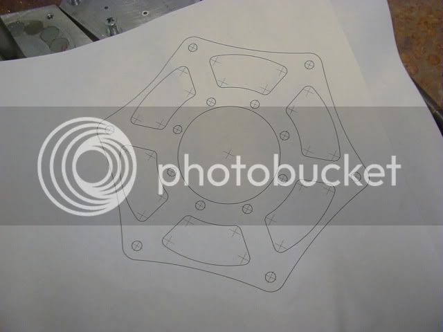
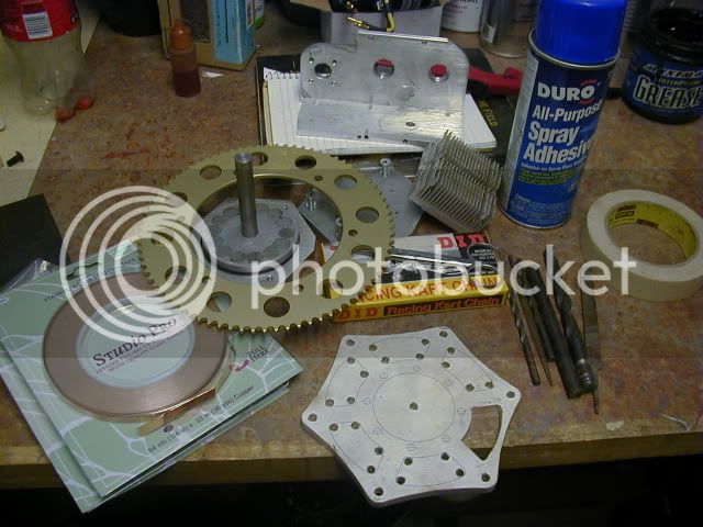
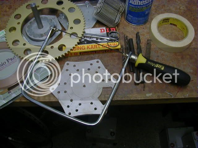
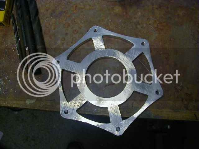
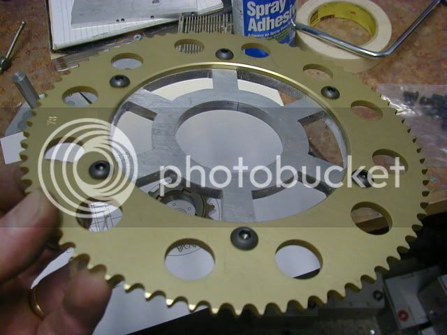
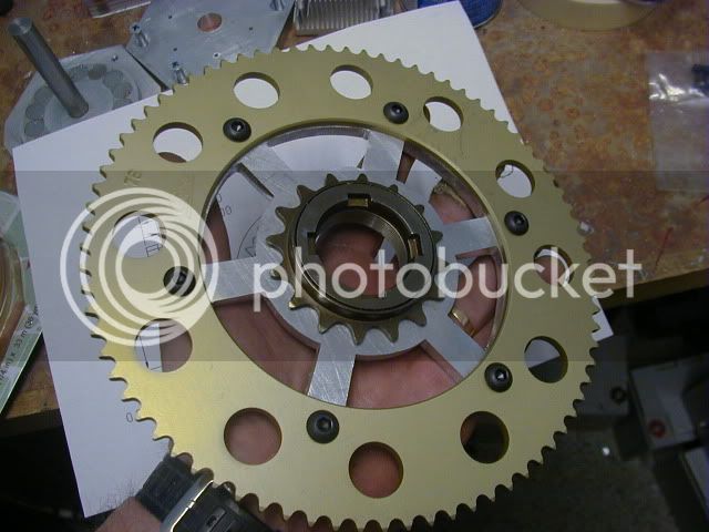
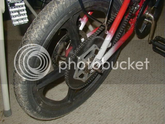
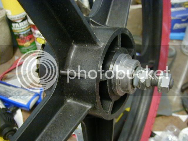
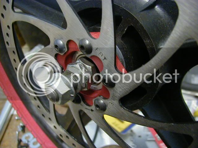
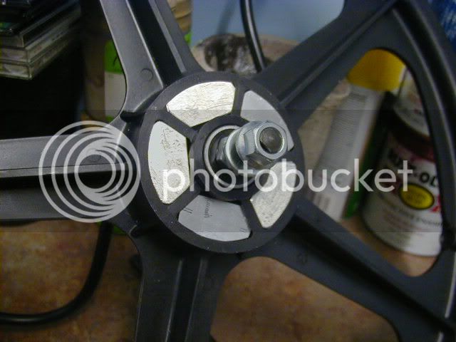
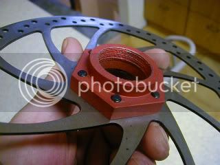
The adapter is a one off- but a simple fabrication...the disc bolt circle is 44mm & the internal is a somewhat standard 30x1 mm thread (small BMX). I sorta fudged it as & don't have a proper pick gear to do a 1mm thread. it becomes a Jam fit for the last 1/8 turn onto the hub.
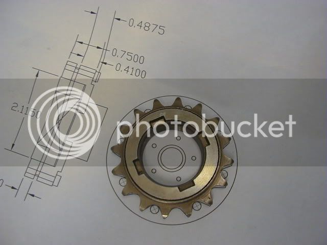
Here is a better pic of the rear adaper:
P9150014.jpg


No problem bringing up controllers. All of my work is focused on the big outrunner's....& using the existing magnets to trigger the hall sensors.
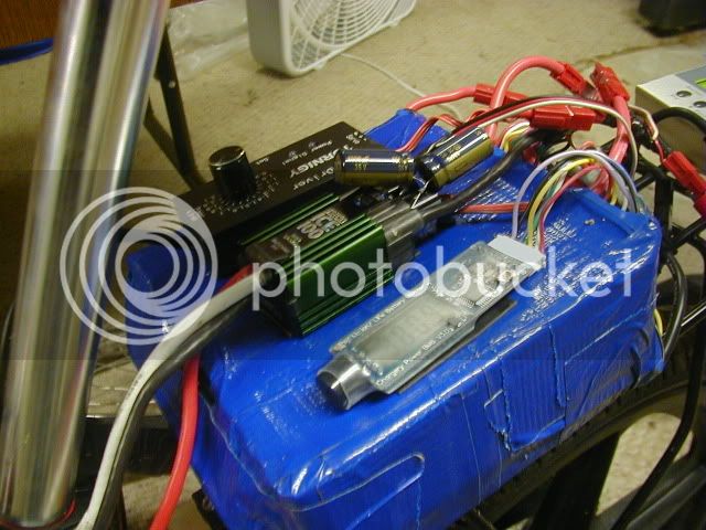
I bought a batch of 12fet infineons from the e-crazy man awhile back just for side by side testing & have been giving myself some lessons (learning by watching over the shoulders Of Mr Harris & Ricky in NZ) on controller assembly & operating. I am getting good results using irfb3066 fet's in them after making the R43 Mod to side step the over current interupt circut. The only issue is, I am limited to 60v Max......I have bugeted for some irfb3077's to push back up to 72v if i think i need it...These are like thoses mr Lyen provides....Just without all of Edwards fine work in them.

Hall sensors on outrunners:
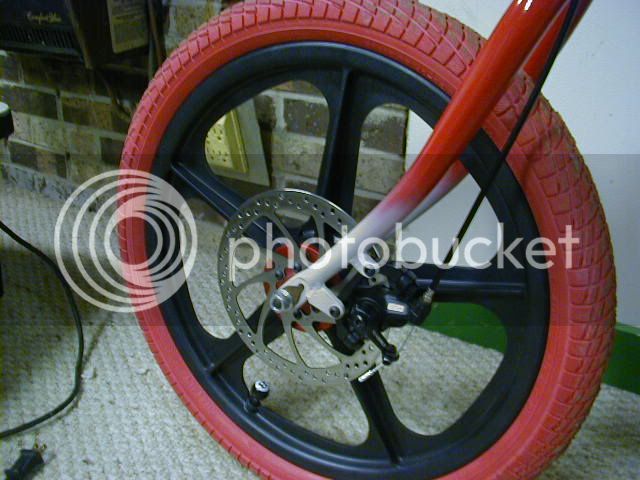
Using Burties size optomised 17.14deg spacing has been good & bad...on the smaller 63mm motor, it seem's to perform perfectly....I can reset the zero position in several spots about the can, & adjust the timeing up & down & get the predicted results...powers the bmxer fine with a modded 6fet (4110's in it) @ 48v other than being current limited...it just works.

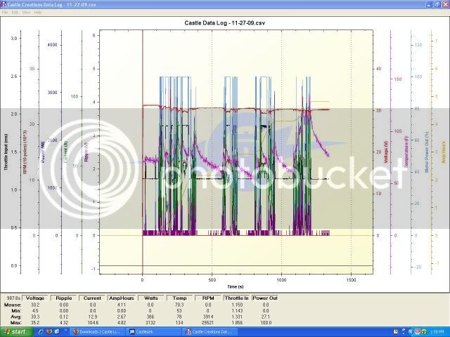
The Casle hv160 pulls a bit stronger through to top speed,(quite a bit actually) But under max (really stupid max) load I can hit the current limit. Then weird things happen. 50% of the time the motor will revers...(???) After freewheeling to a stop I have to unplug to reset the controller to get rolling again.

The mid throllte/RC controller issue is: Unbelivablely high current spikes generated when the controllers are chopping the current (pwm)...under heavy load & partial throtle (flyback effect?) the FET's don't have the theramal disapational ability to survive. This is compounded by the small size & Fet package in RC controllers.(I'll not scare any one with a photo of an exploded controller :twisted: )

I won't say you can't build a nice reliable RC set up....You Can....I am saying that I can't trust a singe hv160 to perform reliably within my objective.

The larger 80mm motors arent so forgiving. After Burtie reported his motors seem to favor internal mounting, I started to reposition the halls about the can...& my 80mm motors are far more sensitive to position & timing changes...there are sections where it gets really wild results under load.....this all went away spaceing the halls out to 120 deg...& works = as well at 60deg. Burtie speculated the magnetic feild in the biger stator motor may be jumbling the signals of the closely spaced hall set up....I don't have any sophisticated equipment to measure any of that mojo...but the logic & results seem to support that theroy. I am up to load tesing on the bike with 60deg halls.....I just need to get through the 3 feet of snow outside :(

when Burties programable electronic timeing units are perfected, this will all become mute points & "old school" thinking :lol:

I have High Hopes for Jeremys simple controller design using the TO227 fet package...it should be able to withstand the abuse from the small high rpm motors at least 3x better than the T0220 fet infineons

You are running the Astro's IIRC? I havent seen a real solution to the Hall placment on those yet.

Call Out to DrewJet: How about an update on your Asto experimants...are you using halls on your Mnt bike?

JohnRobHolmes is close on having it figured out on his 12kw astro's.......The Astro's are a bit easyer on the controllers only being 4 pole motors (if I understand the phisics correctly) & The higer resistance Wye termination will also releive some stress regarding Phase current spikes.

I just recived a new (still cheap) Video camera so I will try to get something to show regarding halls/outrunners in the motor section in a few days.

That catches up every one on the ellectrical side of thud's shop.....got a few things brewing that will be fun to share when the timings right.
Have fun gang.
Oh yea, here is a video of the bike finaly
https://www.endless-sphere.com/forums/viewtopic.php?f=28&t=18578&start=75#p276042
 
Hey Thud,

Thanks for the info on the adapter and photo - exactly what I wanted!

And thanks so much for your detailed explanation of the state of controllers - really helps a lot.

The RM7 is still on hold awaiting more information - it's such a cool looking bike I have real incentive to get it going but still do not feel confident about controllers yet.

I am working on two machines at present and hope to get them both done by Earth Day here in So Cal, 1st & 2nd weekends in April. More info in a new Cortina thread I will start in a few days.

Thanks again for your help and good will. Great good luck with your racing endeavors.

Roy
 
Where can I find a video of this bike running?? :eek: :eek:
 
Heres one
https://endless-sphere.com/forums/viewtopic.php?f=28&t=18578&hilit=ohio+race&start=75#p276042
 
Back
Top