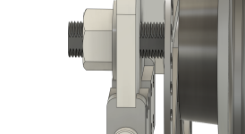
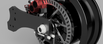
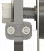
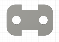
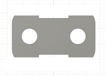
torque arm picture thread

There you go. Maybe a little plate under the nut too to distribute the load across all 3 plates. With some decent hardware and if it's cut from some high carbon steel it will be able to clamp plenty tight.

I wonder what Chalo, as a former machinist, thinks. :mrgreen:
 
chuyskywalker said:
heh, see edit :D

I like the plate (under bolt head) thickness in the original more. Looks to be 2x thicker. If all part tolerances hug the bolt really well, and made from hard steel, having essentially an un-bendable plate under the bolt head and under the nut reduces a lot of the shearing forces the other bolts will experience.
 
Comrade said:
I like the plate (under bolt head) thickness in the original more. Looks to be 2x thicker. If all part tolerances hug the bolt really well, and made from hard steel, having essentially an un-bendable plate under the bolt head and under the nut reduces a lot of the shearing forces the other bolts will experience.

Agreed; I'm trying to stick to two plates thicknesses (.125" or .250"; figure those are common, readily available stock sizes) and was playing with the end-plates being thinner. But I see your point; thicker on these makes more sense. Plus, this design really does put a lot of pressure on those through-bolts.
 
Comrade said:
There you go. Maybe a little plate under the nut too to distribute the load across all 3 plates. With some decent hardware and if it's cut from some high carbon steel it will be able to clamp plenty tight.

I wonder what Chalo, as a former machinist, thinks. :mrgreen:

There's no advantage in using a material that's harder than the axle, because in that case the axle will be the part that smushes when times get tough. A little superficial comparison testing with a file or prick punch will let you know if you're in the right ballpark. Most hub motor axles don't seem much harder than common structural steel.

The wider the section (along the length of the axle) being [strike]cleaned[/strike] clamped, the more torsion it can take without damage. But as Amberwolf points out, then the next weakest link is the root of the axle stud where it steps up in diameter. So there are inherent, inescapable limitations. The best you can do is hold both sides in a way that doesn't allow back-and-forth movement between the torque arm and axle, and has enough width to resist material yield. Beyond a certain point you'll only insure that any failure will be in the axle rather than the TA.
 
Chalo said:
The wider the section (along the length of the axle) being cleaned, the more torsion it can take without damage.

That's the weak point that I see in this design. The clamping design has at least 500% safety margin. :mrgreen: But if the material of choice for the center plate is 1/4", that's not that much metal on the axle. What's the expected torque of this motor?
 
In my limited experience 1/4 inch fasteners as fairly easy to twist off (regardless of the rated strength).
One can get 2D laser cut (or water cut) parts in 3/8 and 1/2 thickness as well.
That would allow one to use high strength (grade 5 or 8) 3/8 fasteners.
 
The circumference of a 12x10 axle is 35.42mm. 1/4" plate is 6.35mm thick, so if the axle is perfectly hugged by the plate, that's 0.349 sq. inches of contact area. Say the plate and axle is pretty soft 50k PSI yield steel, that's 17450 lb. yield strength. For a midsize motor with say 50nM torque, there is a healthy margin even if derated for the fact that the axle is threaded and really roughly half of the axle circumference is resisting spinning. If there are 2x clamping torque arms, even more so.

Screen Shot 2023-01-14 at 1.09.07 PM.png
 
Comrade said:
The circumference of a 12x10 axle is 35.42mm. 1/4" plate is 6.35mm thick, so if the axle is perfectly hugged by the plate, that's 0.349 sq. inches of contact area. Say the plate and axle is pretty soft 50k PSI yield steel, that's 17450 lb. yield strength.

And yet I've seen a few such axles running on 36V/20A or similar, that carved right through both a cheap torque arm and the dropouts.

I've also seen properly tightened setups that only used tabbed washers and had no such problems at the same power levels.
 
Chalo said:
that carved right through both a cheap torque arm and the dropouts.

I suspect that oversized holes was the only problem. Not the materials. 12x10 is pretty close to being round, and if the hole was 11mm instead of 10, which I think it's about average slop for cheap forks and torque arms, then the contact area is significantly reduced, and the spreading force increases to boot.

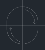
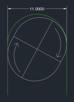
The significance of that extra 1mm is much easier to see when visualized.

All else being equal, a clamping torque arm should do much better.

Screen Shot 2023-01-14 at 2.49.32 PM.png
 
Comrade said:
The circumference of a 12x10 axle is 35.42mm. 1/4" plate is 6.35mm thick, so if the axle is perfectly hugged by the plate, that's 0.349 sq. inches of contact area.
I can't tell if you accounted for this or not:

The axle contact area that resists torque against the plate is *only* the flatted surfaces. None of the threaded area does this (not counting any nuts or other hardware you may have, just the clamping torque plate).

What is the surface area of the two flatted surfaces of the axle that are in contact with the clamping segment of the 1/4" thickness of torque plate? (I measured this once upon a time for a 12mm and a 14mm axle on a motor here, but I can't remember)

(thicker the plate, the greater surface in contact between them that is clamped).

(larger the axle diameter, the larger the flatted surfaces of it will be)
 
Comrade said:
Chalo said:
that carved right through both a cheap torque arm and the dropouts.

I suspect that oversized holes was the only problem. Not the materials.
The relative hardness of the materials does make a difference (as does the size of the flatted areas, as also does if it is a closed hole (or clamp) vs open-ended dropouts.

See my posts earlier in this thread about the damage caused by the harder axle of the Ultramotors vs that of the typical hubmotors (that were at much higher power and torque, enough to even break those axles, vs the UM at lower power and torque).
 
amberwolf said:
The axle contact area that resists torque against the plate is *only* the flatted surfaces.

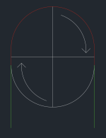
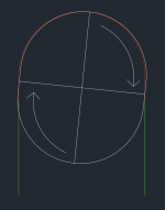
Not sure about that. I think the area in red will be resisting torque, just to different degrees at different points.

Screen Shot 2023-01-14 at 4.03.16 PM.png

There is much more contact area that just the flats.

Screen Shot 2023-01-14 at 4.13.29 PM.png
 
I was thinking.... a 2 piece insert that actually "hugs" the axle should double the contact area. The whole thing can be covered and held together by a 1" washers front and back, which probably would have been used anyway.

Screen Shot 2023-01-14 at 5.33.25 PM.png
 
Comrade said:
I was thinking.... a 2 piece insert that actually "hugs" the axle should double the contact area. The whole thing can be covered and held together by a 1" washers front and back, which probably would have been used anyway.

This is probably a bit too extra -- both from a making stand point, construction, and overall effect. As to the effect -- consider that the non-flat areas of the axle are threads; they aren't a flush surface and likely have extremely limited surface area by comparison.

ZeroEm said:
Thought the fast rule for thickness was 3/16", that 1/4" was not enough.

It would, technically, be 1/2" since it's on both sides.
 
chuyskywalker said:
I was thinking.... a 2 piece insert that actually "hugs" the axle should double the contact area.

Over-engineering is half the fun. :lol:
 
Not 1/4", but
https://www.bikeforums.net/electric-bikes/1228351-how-protect-hub-motor-axle-thread.html
https://cimg1.ibsrv.net/gimg/bikeforums.net-vbulletin/1632x918/strip_a9535a95b84a4d264a5d3eb711d5ba1a5d74ab1e.jpg
strip_a9535a95b84a4d264a5d3eb711d5ba1a5d74ab1e[1].jpg
https://cimg8.ibsrv.net/gimg/bikeforums.net-vbulletin/995x565/striprote_8607b1ce82a60626108743832d559719ab86e91a.png
striprote_8607b1ce82a60626108743832d559719ab86e91a[1].png
 
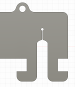
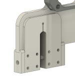
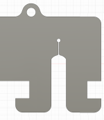
I've been continuing to tool on this and figured out there's a flaw in the design. Specifically, there is a gap in between the arm and the motor the requires washers. Except if the washers on are on the axle, you won't be able push the axle into the dropout without hitting the bolt-on plates. (Not without having to bend the arms apart, yuck.)

2023-01-16 13_20_30-Window.png

But, I have discovered that there is more room between the arms and motor than I was thinking. All the exploration into brake fitment has made me realized brake adapters are all 10mm wide, so if I go back to this idea:

chuyskywalker said:
Comrade said:
Something along these lines. I'm not much of a 3D modeler.
I see what you're getting at, there's a lack of room on the rear of the plate, but here's something towards what you were talking about I think:

There is totally room for this setup.

2023-01-16 13_14_56-Window.png

This makes manufacturing much easier as it's all the same thickness and there are only two designs (3 pieces + bolts).

2023-01-16 13_16_46-Window.png
2023-01-16 13_18_42-Window.png
2023-01-16 13_17_43-Window.png
 
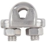
And that setup can also be used with just the main plate and the clamp from one of these

with a long enough U-bolt, should a DIYer not want to / be able to make the small plates.

THere are square-end Ubolts as well.

A quick search didn't turn up a narrow enough version of either for this that was also long enough...but if one has the tools and skills to make the torque plate, one may also be able to turn a length of threaded rod into a sufficient Ubolt. ;)

A J-bolt could also be used, if the cable clamp has or can be filed to a wide enough slot to go entirely over the plate edge, so the nut end is also secure.
https://www.bosunsupplies.com/J-Bolts-Stainless/

chuyskywalker said:
I've been continuing to tool on this and figured out there's a flaw in the design. Specifically, there is a gap in between the arm and the motor the requires washers. Except if the washers on are on the axle, you won't be able push the axle into the dropout without hitting the bolt-on plates.
If you used C-washers (or cut a section out of regular ones), you can just drop them onto the axle from above after it's installed (or at least, for the ones that won't fit on while installing the axle into the plate slots). I did this for some of my hubmotor stuff on CrazyBike2, and the early SB Cruiser and other builds, for similar reasons.

Or you can add that spacer to the stuff to be machined, as a single C- or U-shaped piece to drop over the top, of full thickness. Or multiple sections if that's too thick. Saves dealing with a lot of separate washers.
 

Attachments

  • 17139735.jpg
    17139735.jpg
    9.9 KB · Views: 55
amberwolf said:
A quick search didn't turn up a narrow enough version of either for this that was also long enough...

I did some digging around too, but couldn't turn up a u-bolt with an ID of close to 3/8", most seem to start at 9/16" which is a bit too wide. I think, also, that you would have to use a square one, and even then, compared to the flat piece of 3/8" material, it'll be no contest which one holds better.

amberwolf said:
but if one has the tools and skills to make the torque plate, one may also be able to turn a length of threaded rod into a sufficient Ubolt. ;)

Alas, my intention is to have these laser cut professionally, so I not only lack a fiber laser (lol) but also do not have a lathe :D

amberwolf said:
chuyskywalker said:
I've been continuing to tool on this and figured out there's a flaw in the design. Specifically, there is a gap in between the arm and the motor the requires washers. Except if the washers on are on the axle, you won't be able push the axle into the dropout without hitting the bolt-on plates.
If you used C-washers (or cut a section out of regular ones), you can just drop them onto the axle from above after it's installed (or at least, for the ones that won't fit on while installing the axle into the plate slots). I did this for some of my hubmotor stuff on CrazyBike2, and the early SB Cruiser and other builds, for similar reasons.

Or you can add that spacer to the stuff to be machined, as a single C- or U-shaped piece to drop over the top, of full thickness. Or multiple sections if that's too thick. Saves dealing with a lot of separate washers.

Yeah, but that ends up being extra hassle and more pieces. I did, actually, considered a straight up full wrap piece on the backing plate, like this:

2023-01-16 15_18_00-Window.png

But it's more economical to go with the two-bolt, custom plates setup.
 
That's a much simpler design for sure. I'd beef up the "hooks" a little, maybe 50%.

And remove superfluous metal from the perpendicular bolt plates. All that overhang that's not under the bolt heads isn't really doing anything.

1.png

2.png
 
chuyskywalker said:
amberwolf said:
but if one has the tools and skills to make the torque plate, one may also be able to turn a length of threaded rod into a sufficient Ubolt. ;)

Alas, my intention is to have these laser cut professionally, so I not only lack a fiber laser (lol) but also do not have a lathe :D
Not sure how you could use a lathe to make the Ubolt from threaded rod?

For 1/4" threaded rod you could reasonably easily use a vise and hammer for a crude square-U-bolt (just avoid hitting any of the threaded areas you actually need to put nuts on), there are other hand tools that could do it too.

With a welder and grinder (or files and patience) one could cut 90 degree angles out of the areas you are going to bend, then bend them, then weld them together that way (covering the threaded areas at the rod ends with something to keep spatter from corrupting the threads).


Yeah, but that ends up being extra hassle and more pieces. I did, actually, considered a straight up full wrap piece on the backing plate, like this:

2023-01-16 15_18_00-Window.png
Which also improves clamping surface area.
 
Back
Top