torque arm picture thread

Ok, so I have been looking over this thread, and love all the great designs, and came up with my own that I would like critiqued:


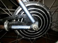
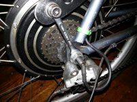
(Sorry for the awkward angle, but it might make more sense if you look here too at my E-Bronco Build as this is going on a stretched cruiser as Mid-Drive: https://endless-sphere.com/forums/viewtopic.php?f=28&t=44997&start=25)

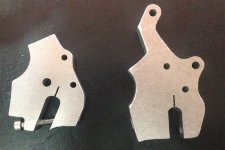
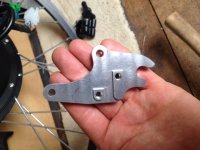
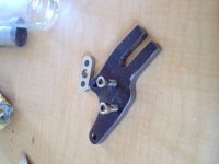
The idea is to have a 1/4" steel bracket coming from the clamps on the seat post, made in sort of a BMX style "drop out" but then take four 2 - 3" lengths of 1/2" square rod of mild steel and have them bolted to the plate horizontally, and on the ends have vertical pinch bolts.

I intentionally made the space wide so that I could use this to tension the chain and then clamp it down as this way I would always have a good solid attachment between "torque clamp" and Hub Motor Axle, allowing for the slight size variations of axle thickness.

Please critique!

Thanks in advance - 8)

Torque%20Clamp%204_zps4lrvanix.jpg


[moderator edit to add pic]
 
Made a scaled Drawing of the "torque clamp"


*** edit ***

I just realized that the last two horizontal screws on the right side need to be countersunk (make room for the axle nut) so I am changing all the horizontal screws to countersunk.
 
Shouldn't the pinch bolts be as close to the axle as possible?

Shouldn't the torque handling bolts be as far away as possible?

Chain tension options:

1:Chain tensioner
2: Eccentric bottom bracket
3: No chain
 
diff_lock said:
Shouldn't the pinch bolts be as close to the axle as possible?

Shouldn't the torque handling bolts be as far away as possible?

Chain tension options:

1:Chain tensioner
2: Eccentric bottom bracket
3: No chain

As this is a mid-drive, chain is how the power gets to the rear wheel.

I agree that you want the pinch bolts close to theaxle as possible, however, the compromise is both for the ability to slide the axle for tension, and also to make room for the wiring to exit on the non-drive side.

If I can get away with the pinch bolts both being on the inside, I will, but I fear that will not allow for enough space to both tension the chain or allow both that AND room for the exiting wires on the CroMotor on the non-drive side.
 
20s of 5000mAh turnigy ~2500W through generic 1000W hub, Lyen Mark II
The bike is a Marin Pine Mountain. The dropouts seemed pretty beefy amongst first glance after buying it via craigslist. I ran 48v and ~1400W and 72v ~2000 for a few weeks without any problems. Attempting to true my rim I noticed that my axle was starting to slip so I modified a crystalyte torque arm that I was using on my old bike. The axel in the vertical dropout alone has a significant amount of play. And the torque arm can even be rotated a few degrees on the axle. The vertical dropout allowed me utilize half of the crystalyte torque arm on one side and the other half (and a small wrench) on the other side. I haven't noticed any slip since the addition of the torque arms. It's been holding up pretty well for the first 100 or so miles.

Do you think this crystalyte torque arm pre loaded one way any the and a drop forged 10mm wrench preloaded the other way will suffice for the "rocking" motion that will occur if I enable regen braking? Keep in mind I'll be running 2000+ Watts and using regen at 30+mph.
 

Attachments

  • 20160105_182404_2.jpg
    20160105_182404_2.jpg
    112.4 KB · Views: 4,166
  • 20160105_182255.jpg
    20160105_182255.jpg
    124.9 KB · Views: 4,166
I like the idea of the fully floating pinch plate for sure. A variation on the idea I used with two angle irons.

Much better IMO, than the designs that flex a slot closed. If you think about it, they pinch more on the open end, and may not pinch at all on the closed end. Having at least one side float allows you to tighten down hard on both sides of the axle flat.

Disadvantages, it's only as strong as the bolts. I'd say, go ahead and beef up the steel. make it 3/4 thick, so bigger, stronger bolts can be used.

Zero reason to have a nut once it's pinched hard, so I would not worry too much about that. And one piece can just be welded to the plate. Bolt if you like, but it can be welded. only one side needs to float. The floating side needs no bolt to the plate, but if you like, you can use a bolt there too.
 
View attachment 1Screen Shot 2016-01-22 at 9.20.30 PM.jpg

This one has been working well for a while now. Its a low power bike so I used the welded up spanner on one side and a slice off of a Dr Bass TA on the other side. The DR Bass TA is about half of its normal thickness and then I just riveted it to the drop out on the one side.
 
Here are some pics from the finished product, I have yet to put it under power, but I think you're right Dogman, 3/$' might be even better, as I am making the countersinks the same diameter as the pinch bars, so I will probably use 3/4" mild steel instead of 5/8 next go around, but I think this will suffice for testing at least.


I'm building a bike for my neighbour- when he went out and bought a voodoo wanger the pressure was on to make a clean build. It has bolt on sliding dropouts for the rear wheel so that the hipsters can ride their fixties to the cafe. I took the piss weak aluminiumn dropouts ( it's sposed to be a mtb- wtf! I wouldn't trust them remotely) and copied them in 8mm steel. Just a few simple tools- but a mates tap set came in very handy. One each side so 16mm all up. I was going to do clamping but I reckon this wil be fine! It's only a 1000w (28mmstator) hubby. Makes it easier to get in and out.
I've since added two more fixing bolts cause in this pic, its not quite finished.
K
 

Attachments

  • image.jpg
    image.jpg
    47.5 KB · Views: 5,637
  • image.jpg
    image.jpg
    35.3 KB · Views: 5,637
Here is mine from ebay uk, "Torq - eyelet style". Good fit and does it's job well. Have a standard damped fork and used a rubber-P-clamp to attach the lever.
 
The new leftside clamping dropout (inner axle, left wheel on SB Cruiser), from this post:
https://endless-sphere.com/forums/viewtopic.php?f=2&t=67833&start=275#p1150017

file.php


file.php


The outer axle of the same wheel, I welded an ex-BMX dropout to the axle stub, cutting off all the rest of the axle past that point as it's just something to catch on doorways and such. Once i find my tap-and-die set, I'll drill and tap holes for very small bolts to secure that plate to the plate under it on the trike itself.


From last May, when I made the first of this type of dropout for hte x5304 on the right wheel
https://endless-sphere.com/forums/viewtopic.php?f=2&t=67833&start=125#p1048533
First it was just a big thick dropout,
file.php


and then made clamping here:
https://endless-sphere.com/forums/viewtopic.php?f=2&t=67833&start=125#p1050001
file.php
 
From "ridethelightning" (Erik in Australia). Four water-jetted/laser-cut steel plates laminated. The three central plates have a cutout for the clamping bolt to pass through from the front to the rear. The four outer plates hold the clamping bolt in the center (two on each end), and the square "washer" compresses all seven plates.

The torque-plate is attached to the stock disc brake caliper mounts, and the actual caliper is attached to the torque-plate. Very clever!

file.php
 
Migueralliart, I can't wait to get your curved torque arm in the mail, I've been checking usps tracking religiously :lol: If its actually as strong as it looks ill probably melt my cheepo 1000 Watt hub before cracking any dropouts
 
It would be cool to get a 3d printer to make 3d designed torque arms. it would take 5 minutes to measure the design, 20 minutes to get a 3d file for it, and less than an hour to print 4-5 of them, including connection tubes between the copies so that i can pour metal into a mould and do them all in one smelt.

After that you can pour them out out aluminium with space to fit in a blade of chrome vanadium on either side of the clamp, so that it would be a dual material torque arm.

perhaps it would be possible to make the torque arm out of carbon fiber because it's alot easier than smelting it and use brass sheet to hold the actual metal, a bit of epoxy glue would fasten the brass into the right position to hold the axle: http://www.ebay.com/itm/3mm-200mm-200mm-Brass-Sheet-Plate-/111387041978

it would be faster to make 4 carbon fiber - brass torque arms than to make a steel one... todays work. this was 4 hours of work easily. 1/4 inch thick, will probably last a year on my 35 ampere bike. CAM00371[1].jpg

only thing i don't know about is wether to harden this steel at 300C, probably leave it as raw mild steel.

The bike is a centurion low ratio system bike, there are similar lRS bikes from merida http://cdn.coresites.factorymedia.com/bikemagic_new/wp-content/uploads/2004/06/merida_mission_04_side_big.jpg
 
This is two pieces. The bottom is a CNC machined disk brake adapter I bought on ebay for a motorized bike. It's aluminum with a slot that jams it in the drop out. I filed the round hole to fit a 12mm axle.

Over that is my fabbed torque arm, which bolts to the rear rack mount holes.

torque_arm.jpg


Then I added a brace so the disk brake mount is better locked to the frame. Calipers sit upside down.

arm.jpg
 
10mm bolsters for huge cruisers.
315562a08c0f1b0576c018826377c9cf.jpg


Sent from my iPhone using Tapatalk
 
What do you guys suggest for these dropouts?
1.5kW motor, I can use a drill press and angle grinder, maybe also laser cutter.
hOW5PVR.jpg


sEDHeqG.jpg


The main problem is that there are no flat surfaces. I was thinking of cutting something like this out of maybe 8mm steel and then attaching with 3 U clamps like that.

Q7U3cyP.jpg
 
Steel fat bike front fork with 500W motor. Kind of flimsy but it was cold in the garage, and I wanted to try out the FWD.. My uneducated analysis said any movement of the arm would translate to an up/down motion parallel to the forks, and a clockwise twist would bottom out the middle bracket against the end of the fork.

Doesn't matter. The nursing home attendants took away my fatbike for the winter. Cable was upside down anyway.

P1510842.jpg
 
Back
Top