Tsdz2 firmware open source adapted to vlcd5, vlcd6 and xh18

the gear sensor (and brake lever sensor) works by grounding the signal line.

so if you parallel the gear sensor with a speedo sensor, the gear sensor will ground the speed signal, preventing the system from knowing what speed it is at.

what happens at that point depends on the system firmware.

if the firmware is setup to cease motor output when no valid speed signal exists, but resume the motor output as soon as a valid signal exists again, then it would shutoff motor output only exactly as long as the gear sensor signal was "on" (grounding the speed signal).

if the firmware is setup to do something else when no valid speed signal exists, then the behavior will follow those rules.
 
does it work fine with a *grounded* speed signal?

(the speed signal is likely pulled up internally, just like motor hall sensor lines are, and is grounded by the speedo sensor itself periodically to generate the speed signal).

if it operates the same whether the speed signal input is open or grounded, regardless of any speed-signal-related settings, then there's no way i can think of that would allow grounding that signal by the gearsensor to change the operation of the system at all. :?
 
eyebyesickle said:
I am quite interested in this. The only way I can see the gear sensor working when hooked to a speed sensor port, is if it makes a temporary spike in the speed sensor pickup, tricking the system to thinking that it went over the speed limit and causing a temporary cutout... Is that what you accomplished? If so, does it affect the odometer just slightly I would suspect? I'd be interested to hear any more info... This is definitely new to me...

Thank you for your interest for this potential improvement. I am sure that it has to be confirmed by other people here.

As I first bought a Bafang and discovered (I am stupid in some way) that my coast brake did not work any more, I spent another 315 € to buy a coaster brake TSDZ2, with an XH18 LCD, much smaller, more effective to change PAS, than the central Bafang C965 (sorry to say that but I don't need a temperature sensor and a large LCD because the motor is supposed to work and stop before burning, as for the battery). But, as explained on my first video, I bought simultaneously the BBS01 motor, battery and gear sensor at the same place (and I got a 30% return on the total, from the Ville de Paris which is promoting pedelecs in central Paris). Therefore, I installed the gear sensor at that time (and at the very end of the shift cable, close to gear hub).

The gear sensor was mandatory for me because I had read on a German forum that it was mandatory to not damage the chain and the gear hub. And they were right, it was much more comfortable and secure with this gear sensor installed.

Also, as already said, recent BBS have a new gear sensor output cable, of an adequate length, in order to be plugged strait away to the Bafang 3 pin connector of the gear sensor.

When installing the TSDZ2 with its native stock firmware, I let the gear sensor in place but unconnected because I did not know how to connect, and if was possible to connect it. While installing the first motor, the Bafang, I kept the lights circuit in place with its original front hub dynamo; therefore the second connector of the Tongsheng speed sensor was free (free for installing the Bafang gear sensor with an adhoc cable...).

Fortunately, with the stock TSDZ2 firmware, it was not necessary to have a gear sensor connected. I was very doubtful, expressed my doubts on a different forum, but after some kilometers I was convinced.

And then came the Open Source firmware story because I had read that the TSDZ2 controller could be modified in order to control the motor in the same way as the Bafang and even as the Bosch! And it is true that I really appreciated the Bafang and was a little disappointed by the TSDZ2 which made me to tired after my 25 km in central Paris every day.

I really appreciate the Open Source firmware which behaves as good as the Bafang. I have had some difficulties to understand who did what, tried to reconstruct the paternity up to Stancecoke who maintained probably the most useful github fork of Casainho, Marcoq, Mbrusa etc works (I forked the Stancecoke fork in order to adapt the Java configurator to OS/X and Linux too).

Sorry for this long story and I will try to respond to eyebyesickle
  • As said by ilu, "apparently the gear shift sensor works as the HWB sensor". Thus here is again the wiring
    • Tongsheng 6 pin male <=> Bafang 3 pin female (Higo 3 type B, orange connector)
      • 1 orange ground; <=> 8 black ground;
      • 2 white (speed sensor). 5V or nothing; <=> 4 blue (brake signal or speed sensor or gear shift sensor);
      • 4 green (+ 5V for light) <=> 6 red 5V;
    thus the 1(=8= Ground) and the 4(=6=+5V) are easy. The hidden wire brake sensor needs this 5V and, when used, connects the pin 2(=4) to the ground 1(=8), during 2 seconds (as Rydon said if I understood him correctly).
    (New Edit: +5V is on position 4 for Tongsheng, TSDZ2 wires are described for example here and Bafang there)

    Here, with the gear sensor it is exactly the same process but it lasts as Rydon said 800ms only.
Now, when hooked to the speed sensor what happens? As said earlier, I think that the 800ms cutoff is adding a parasite signal to the speed sensor signal. And, apparently and fortunately, the controller is able to manage this erratic signal correctly.
For me it behaves as if you take a second magnet and approaches it randomly in front of the speed sensor head while the wheel is turning at a regular speed. How does the firmwares (and which part of if, Program, EEPROM?) react, that is the question?

  • Apparently, and according to my short experience it behaves well and the controller is not affected at all by the gear sensor signal.
  • At all?, well my first concern was to verify that the 25 km/h upper legal speed was not affected by this gear sensor and I can say that it is not.
  • eyebyesickle: does it affect the odometer just slightly I would suspect? . Yesterday while biking close to a colleague I asked to verify the speed meter, it was 23km/h for both of them. Odometer I have to try with exactly the same path to work. It will be very close, I am sure, even if I shift gear speed every 20 seconds or so.

Regards,
Revher
 
Assume the speed signal is a voltage that is pulled to gnd every time the magnet passes the sensor.
The fastest way to measure speed would be to measure the time between 2 of those pulses.
If there is no filtering and you inject an extra pulse with the gear sensor, it will increase the speed readout, depending upon where it appears between 2 speed sensor pulses.
If your system is programmed for a 25km speed limit, that speed increase might stop motor assistance for a split second.

That's a way how I see it could possibly be working..?
 
I've been watching this closely because I use a Nexus 8 on my handcycle. Because my arms are so weak I have my TSDZ2 turned up so that I put in 100w and it puts out 600w so I have to let off the pressure on the pedals for each shift and it would be awesome if using this sensor would automatically do that for me, so I don't have to let the pressure off and then apply the pressure again.
Sounds like there are 2 different ways to do this. One is to connect it to the brake sensor which may be too long of a power down but will continue to work regardless of the firmware. The other is to hook it to the speed sensor and for some reason, it's working correctly at this time and the power down is about the right amount of time. If we can find out exactly what's happening and how then as the firmware evolves it will continue to work correctly and maybe we can set the power down timing.
 
The brake input is designed for that purpose.
The fact it works on the speed sensor input is nice but likely not something programmers will test every time they bring out a new version.
The time the motor interrupts it's assistance is likely the time needed for one wheel rotation. Upon the the next magnet speed sensor pass, the system will redetect the actual speed under 25km / hour and will resume motor assistance.
It should be possible to have the brake input react as fast as well.
 
Thanks,
Does anyone know what the wiring diagram would be to wire the shift sensor to the brake sensor and do they use the same type signal source?
 
I am going to install lm35 temperature Sensor into an eight pin TSDZ2. I don’t want to cut the throttle connection so I’ll solder the three pins onto the controller board. however I’m wondering if I can leave the throttle connector connected and just switch between the temperature sensor and throttle using the firmware . the reason being is that I may want to enable the throttle at some point during the ride.

Is this possible to Have both the throttle and the temperature sensor wired but only one of them is enabled in firmware. ?
 
The temperature sensor and the throttle both use the same analog input on the microcontroller. So you either has firmware with throttle enabled that measures the voltage on that input and gives motor assistance relative to that voltage, or you have firmware that measures the voltage on that input and converts it into the motor temperature. So, if you want both, you would need a toggle switch to connect the throttle signal or the temperature sensor signal to the throttle analog input of the microcontroller. Maybe some day someone will discover a free digital input on the microcontroller and use that to read the temperature from a dallas 'one wire' temperature sensor. If that's the case, the analog throttle input can stay connected to the throttle. After all, it's not like you need 10 temperature readings every second.

The gear switch sensor needs gnd and 5V
If you connect it's output to the brake input instead of the speed sensor input, it should act as if you shortly press the brake when you switch gear. (It simply pulls that input to gnd for a split second when you switch gear.)
No idea if the brake inputs are filtered and if they need a minimum pulse length before the motor assistance is stopped.
If I remember well, the brakes also connect the brake input to gnd when the brakes are activated. On some controllers the operation is reversed and the brake input is connected to gnd when the brakes are not activated. When you activate the brake lever, the brake input signal is disconnected from gnd with those. This has the advantage that a broken wire will be seen as an activated brake and the motor won't run in that case. It has the disadvantage that you can't connect the 2 brake levers to one brake input in parallel. (You can't connect a gear switch in parallel either.)
 
Hi All. I notice there are 48v and 52v versions of this motor available on Aliexpress. Is the motor different or is it just looked for use with either battery in the firmware? There is about a $100 difference between the 48v and the 52v versions.
 
obcd said:
The temperature sensor and the throttle both use the same analog input on the microcontroller. So you either has firmware with throttle enabled that measures the voltage on that input and gives motor assistance relative to that voltage, or you have firmware that measures the voltage on that input and converts it into the motor temperature. So, if you want both, you would need a toggle switch to connect the throttle signal or the temperature sensor signal to the throttle analog input of the microcontroller. Maybe some day someone will discover a free digital input on the microcontroller and use that to read the temperature from a dallas 'one wire' temperature sensor. If that's the case, the analog throttle input can stay connected to the throttle. After all, it's not like you need 10 temperature readings every second.

What about if both the throttle and temp sensor are connected at the same time ?
On the 850c I just change a setting for either throttle or temperature.
As long as I don’t use the throttle lever when temperature setting on the firmware is set , it should be fine ? The scenario would be that the temperature displayed would increased when I press the throttle.

For the setting of throttle in the firmware however that could be a bit more dangerous as when the temperature increased it could cause me to accelerate

So I would need the toggle as you suggest or another way to disable the temperature sensor.

Maybe a y splitter to a toggle button.
I like the idea.
 
lupe said:
Hi All. I notice there are 48v and 52v versions of this motor available on Aliexpress. Is the motor different or is it just looked for use with either battery in the firmware? There is about a $100 difference between the 48v and the 52v versions.

There is only two versions of the motor, 36 and 48V. The only difference between 48V and 52V versions is wether the stock firmware is programmed for 48V or 52v battery. With OSF it does not matter as you can program it by yourself. It's also possible to run the 36V motor with 48V or 52V battery and it gives support at highest cadence.
 
jeff.page.rides said:
Thanks,
Does anyone know what the wiring diagram would be to wire the shift sensor to the brake sensor and do they use the same type signal source?

I have a Shimano 11 speed IGH and find that I need to stop pedalling for a second or so to allow the hub to change gears. This can cause a loss of momentum and riding rhythm. This is partially due to the TSDz2 continuing to power the drive even though I am only applying a little pressure on the pedals. Unlike a Rohloff, the Shimano IGH does require the force on the IGH to be significantly reduced to allow shifting without mashing the gears.

If the 3 wire gear sensor can be used with the 2 wire Tsdz2 brake sensor sockets on rear of the VLCD5 screen, this might allow enough period of loss of engine force to allow the IGH to change gears. Of course the rider will also need to reduce the force on the pedals, but hopefully not need to stop pedalling completely as is currently the case.

(I do not want to use the 'Speed sensor' option as is used by @revher, as my bike doesn't use the 25km limitation)

So my question is the same as '@jeff.page.rides', any suggestion as to to what the wiring connections would be to connect the 3 wire gear sensor to the 2 wire brake sensor on the VLCD5 display.

My testing indicates the brake switch is 'open' circuit when the brake is not applied and goes 'closed' when brake applied. There does not appear to be 5v at either of the brake sensor pins on the VLCD5 display. So maybe the two pins on the VLCD5 brake sensor can be connected to the gear sensor ground and signal wires, and I need to find a 5v source for the remaining wire on the gear sensor.

If I can obtain the wiring details, I will fit the gear sensor to the gear cable where it exits the gear changer mechanism on the handlebar, as it is only a short distance to the VLCD5 display.

Cheers Emma
 
emr said:
jeff.page.rides said:
Thanks,
Does anyone know what the wiring diagram would be to wire the shift sensor to the brake sensor and do they use the same type signal source?

I have a Shimano 11 speed IGH and find that I need to stop pedalling for a second or so to allow the hub to change gears. This can cause a loss of momentum and riding rhythm. This is partially due to the TSDz2 continuing to power the drive even though I am only applying a little pressure on the pedals. Unlike a Rohloff, the Shimano IGH does require the force on the IGH to be significantly reduced to allow shifting without mashing the gears.

If the 3 wire gear sensor can be used with the 2 wire Tsdz2 brake sensor sockets on rear of the VLCD5 screen, this might allow enough period of loss of engine force to allow the IGH to change gears. Of course the rider will also need to reduce the force on the pedals, but hopefully not need to stop pedalling completely as is currently the case.

(I do not want to use the 'Speed sensor' option as is used by revher, as my bike doesn't use the 25km limitation)

So my question is the same as 'jeff.page.rides', any suggestion as to to what the wiring connections would be to connect the 3 wire gear sensor to the 2 wire brake sensor on the VLCD5 display.

My testing indicates the brake switch is 'open' circuit when the brake is not applied and goes 'closed' when brake applied. There does not appear to be 5v at either of the brake sensor pins on the VLCD5 display. So maybe the two pins on the VLCD5 brake sensor can be connected to the gear sensor ground and signal wires, and I need to find a 5v source for the remaining wire on the gear sensor.

If I can obtain the wiring details, I will fit the gear sensor to the gear cable where it exits the gear changer mechanism on the handlebar, as it is only a short distance to the VLCD5 display.

Cheers Emma

I found this item, which appears to be what we need for the Gear shift sensing as it connects to the existing VLCD5 brake sensor sockets, but it doesn't appear to use 5v source. Unsure how it can work without the 5v. It also has brake sensors suitable for hydraulic brakes...
https://www.aliexpress.com/item/33060254663.html

HTB1NDGXXND1gK0jSZFKq6AJrVXal.jpg
 
You should be able to measure a voltage on the brake input when the brake isn't engaged. It can be either close to 5V or close to 3V3. It becomes zero if the input is connected to gnd. (Obviously you can't use it to power your gear switch sensor)
So you basically only have the 5V supply voltage missing for the gear switch sensor.
You can find that voltage on the throttle connector if you have a motor that has a throttle input.
Some people seem to use the 5V light signal on the speed sensor connector. Isn't that only 5V when the light is turned on?
I assume the speed sensor itself is powered with 5V as well, so on it's connector you should find the voltage you need.
No idea if the speed sensor splitter cable has 5V (permanent) on the other (light?) connector.
Another option could be a wire soldered directly to the motor drive pcb. (Like the temperature sensor uses 5V as supply)
 
obcd said:
You should be able to measure a voltage on the brake input when the brake isn't engaged. It can be either close to 5V or close to 3V3. It becomes zero if the input is connected to gnd. (Obviously you can't use it to power your gear switch sensor)
So you basically only have the 5V supply voltage missing for the gear switch sensor.
You can find that voltage on the throttle connector if you have a motor that has a throttle input.
Some people seem to use the 5V light signal on the speed sensor connector. Isn't that only 5V when the light is turned on?
I assume the speed sensor itself is powered with 5V as well, so on it's connector you should find the voltage you need.
No idea if the speed sensor splitter cable has 5V (permanent) on the other (light?) connector.
Another option could be a wire soldered directly to the motor drive pcb. (Like the temperature sensor uses 5V as supply)

Thanks for your reply.

There is no 5v on either of the two brake sensor pins on the VLCD5, either measuring pin to pin or either pin to ground. There is a small voltage (<1v) that decays quite quickly in 1 second or so. This is measuring with a multimeter, so there may be a higher voltage, but as the voltage decays so quickly the meter is unable to read it. (I don't have an oscilloscope).

I am hoping to use the gear sensor near the vlcd5 and avoid running more cables back to the motor. I do have 12v available at the handlebar running a supposedly 5v usb headlight from a DC/DC converter without issue.

I have disconnected the throttle as I have fitted a temp sensor in the motor housing.

Am wondering how the item I linked to in my previous post can operate without the 5v, hmmm.
 
While the typical brakes for VLCD5/TSDZ2 only use 2 pins, these are in a 3 pin connector, and the receiver on the back of the VLCD-5 does in fact have a 5v pin (on all 3 ports, for the throttle, and both ebrakes, even if it isn't typically used)... so it could easily be utilizing this...
 
mbrusa said:
jeff.page.rides said:
When I double or single click the light button to go through the programming it works but also each time it turns the display light on or off.
I understand, but it cannot be done differently.
The control of the lights button is in the display software, it cannot be changed, it always turns the light on or off.
It is only the state of the lights that is used for programming, on or off.
At the first click when the lights come on I cannot know what the operator's intention is, for this reason programming with E02 always starts, if within 5 seconds the second click does not arrive it is clear that the intention is only to turn on the lights, programming is interrupted.
Another clarification, the need for a double click in programming is to not leave the lights on.
Regards

Is there any way to be able to read the parameters when the lights are ON? At least with VLCD6 It seems that when starting from the lights ON state the first long press is ignored considering the parameter-displaying-sequence and only turns the lights off, and I have not figured out any way to check the readings when it is dark, and here in Finland it usually is :(
 
ilu said:
Is there any way to be able to read the parameters when the lights are ON? At least with VLCD6 It seems that when starting from the lights ON state the first long press is ignored considering the parameter-displaying-sequence and only turns the lights off, and I have not figured out any way to check the readings when it is dark, and here in Finland it usually is :(
Unfortunately, the data display can only start with the lights on and end with the lights off.
In the next version there will also be a simplified viewing procedure. When the lights come on, after 5 seconds the data are automatically displayed in sequence, the lights remain on and I also think the display lighting. If the lights are already on, to view the data, simply turn them off and on again. This can be a solution.
Example with XH18, in sequence: motor temperature, battery voltage, percentage of battery remaining.
[youtube]https://youtu.be/rZU4i_6vdig[/youtube]
 
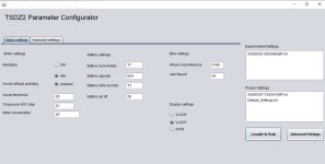
Just wondering if these settings look ok before I flash my controller.
I Have tsdz2 750w 48v 13ah battery with 700c wheels and vlcd5 display. I have also changed the throttle setting to 1 in the advance settings and saved it. any help most appreciated.
para.jpg
 
Battery cut off should be something around 41V.
If you don't have brake sensors, it's not recommended to activate assist without pedaling.
Motor acceleration should be 35% with 48v motor and battery.
Elinx posted a google translated manual some pages back, it is wise to read it before installing the firmware.
here is the link to download the manual
https://endless-sphere.com/forums/download/file.php?id=266384
 
The mbrusa version 0.20beta1a for default displays (vlcd5, vlcd6 and xh18) you can find:
On the github of StanceCoke
The starting guide you can find there too.
Also the manuals for configuration and display

The English translated manuals of the configurator and how to handle the display:
View attachment EN-Configurator -TSDZ2-mb.20beta1.A.pdf
View attachment EN-Manual_display operation-TSDZ2-mb.20beta1.A.pdf


Ashrambo has made an Spanish translation of the configuration file on his blog

Basicly the mbrusa version is the same as latest Buba's build v0.20b for KT lcd3, but some advantages are missing (for now) or a bit more complicated because of the use of these default displays.
Mbrusa is currently working on an improved version of the firmware, in which a number of things should be improved, such as the calibration of the torque and cadence sensor, the overrun and the operation of the display.
You can find more detailed information on the Jobike forum
Some of mbrusa's improvements you can see on Youtube too
 
Is this code already having the latest overrun fixes described on the jobike.it forum or do we have to wait a little longer for that?
 
To date the available code does not include the overrun improvement. It is a porting from the Buba's v.20
 
Back
Top