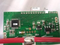
Same specs, too. There *is* one way to find out if it's the same. 
You are using an out of date browser. It may not display this or other websites correctly.
You should upgrade or use an alternative browser.
You should upgrade or use an alternative browser.
Turnigy watt meter for $25
- Thread starter Hyena
- Start date
Ykick
1 GW
That's totally the Turnigy power meter. They got cell log8's too! I bought an iCharger 106B+ from this seller and the deal was handled quickly and efficiently. They seem to have great prices on the equipment, just not Lipo. Yet...
Hyena
10 GW
I bought one of these a few months ago when HK was out - yep they're identical to the TWM. Atleast externally, I didnt bother opening it. Atleast they changed the start up screen to say GT Power instead of turnigy 
Not that turnigy invented this ground breaking product!
Not that turnigy invented this ground breaking product!
adrian_sm
1 MW
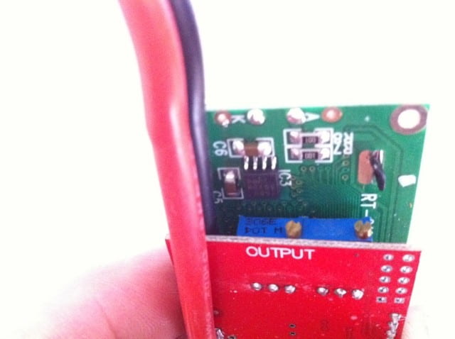
Can you see the little blue adjustment pots on the main PCB. These are quite useful for adjusting the calibration once the remote shunt mod is done.
You should be able to see them without taking the back cover off.They are on the output side of the PCB. Here is a pic of them with the cover off.

You should be able to see them without taking the back cover off.They are on the output side of the PCB. Here is a pic of them with the cover off.
adrian_sm
1 MW
I bought 3 of the GT Power watt meters for EPBuddy at the same time. 1 of the 3 had the calibration pots, the other two didn't.
Looks like it is just luck of the draw sometimes. :?
Looks like it is just luck of the draw sometimes. :?
jateureka
10 kW
SamTexas said:The 2 sides instruction sheet tells me to reverse the direction of the meter when the battery is being charged! ... Does that mean that negative current, power can not be recorded and displayed?
Sam
The Medusa Power Analyser also measures in both directions without needing to change connections but it is no longer being made.
There is a used one on eBay usa right now though...
41south
10 mW
That's a shame that Medusa have stopped making RC products, I've used a couple of their products in RC projects and they were very good 
stanz
100 W
Holy batteries Batman, this is a GREAT product!
I just finished watching the youtube review by Doctorbass. This is perfect for an eBike.
I'm ordering one today, it will help me figure out how good/bad my battery cells are in my L-ion pack build and monitor my pack use in the long term.
I just finished watching the youtube review by Doctorbass. This is perfect for an eBike.
I'm ordering one today, it will help me figure out how good/bad my battery cells are in my L-ion pack build and monitor my pack use in the long term.
skeetab5780
1 MW
ya stanz i use these too they are great little watt meters for the price. first one i owned i smoked accidentally and i just recently ordered and received 2 more from HK. Although i wish they were 100v capable (out of the box) since im now running 20S i only use them while im charging my pack in a 10s configuration. I got an extra one and put some alligator test clips on it so i can use it to check each cell group on the go( smaller than a voltage meter) and cheaper.
Hyena
10 GW
adrian_sm said:Hobbyking are out of stock at the moment, and I was looking for somewhere else to buy these.
Does anyone know if the epbuddy gt-power watt meters are identical internally to the hobbyking ones.
http://epbuddy.com/index.php?main_page=product_info&cPath=8&products_id=42

I would have thought so but I blew one in spectacular fashion the other night under conditions I'd previously run turnigy meters.
I had it all wired up to measure discharge as normal but wanted to quickly check the voltage of a new lipo pack I'd just built. On the turnigys this is no problem, it'll read voltage though the output just won't give you current (but these particular ones must have a diode in them or something.
When I connected up the pack the it instantly got red hot, melted the andersons then then went up in smoke.
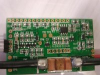
When I pulled it apart I found this:
That's the shunt sitting sideways across the pack of those pots and the IC. It got so hot it melted the solder off the blew it off the board
So yeah, watch out for that guys!
Makes me wonder what would happen with regen...
adrian_sm
1 MW
That is an impressive failure. If I didn't know better I would have said you created some sort of short across the shunt. I can't see how any of the other traces on the PCB could carry enough current to do that to the shunt, without vaporising themselves.
Hyena
10 GW
Yeah I have no idea how it happened. The other side of the watt meter had a 4 pin anderson plug on with 2 of the connectors wired in series but it wasn't plugged into anything so the input side of the meter was technically open. Unless it was a factory fault, I hadn't actually plugged it in prior to that.
It looks like the blob of solder on the +ve side of the board is hanging over the edge. If the shunt had a similar amount of excess solder it may have been shorted and my lipo pack potentially just dumped 250 amps into it. Yep, that'll do it! :lol:
It looks like the blob of solder on the +ve side of the board is hanging over the edge. If the shunt had a similar amount of excess solder it may have been shorted and my lipo pack potentially just dumped 250 amps into it. Yep, that'll do it! :lol:
adrian_sm
1 MW
Ah you hadn't used it before. That makes more sense.
I would put my money on that solder blob creating the short. Looks like the carnage started on the right hand side of the shunt.
Hasn't been a good week for the QC departments of our favourite suppliers....
I would put my money on that solder blob creating the short. Looks like the carnage started on the right hand side of the shunt.
Hasn't been a good week for the QC departments of our favourite suppliers....
Looks just about like (but worse than) the WattsUp I was sent after it's original owner accidentally hooked the controller up backwards to the pack, thru the meter.
http://www.endless-sphere.com/forums/viewtopic.php?f=2&t=21265&start=0

In my case, it was power flowing thru the shunt into the controller that heated the shunt up so much it melted the solder; the damage was limited because the controller's shunts evaporated, disconnecting the current path.
In your case, I don't know what the path was, but it certainly appears as if it was within the meter itself. It *looks* like one end of the shunt got hooked to pack + and one end to pack -.
Since there is no apparent vaporisation of traces or anything, that's the only power path that makes sense, as I'd've expected the PCB to catch fire as the copper traces all vaporized, if it were some other path. But right thru the shunt, there's so little trace involved between the wires and the shunt itself, because of the thick solder, that it could easily handle that for long enough for the solder to melt, vaporizing any flux or other contaminants still within the solder or under the shunt, blowing it out of position during the instantaneous violent outgassing.
http://www.endless-sphere.com/forums/viewtopic.php?f=2&t=21265&start=0
In my case, it was power flowing thru the shunt into the controller that heated the shunt up so much it melted the solder; the damage was limited because the controller's shunts evaporated, disconnecting the current path.
In your case, I don't know what the path was, but it certainly appears as if it was within the meter itself. It *looks* like one end of the shunt got hooked to pack + and one end to pack -.
Since there is no apparent vaporisation of traces or anything, that's the only power path that makes sense, as I'd've expected the PCB to catch fire as the copper traces all vaporized, if it were some other path. But right thru the shunt, there's so little trace involved between the wires and the shunt itself, because of the thick solder, that it could easily handle that for long enough for the solder to melt, vaporizing any flux or other contaminants still within the solder or under the shunt, blowing it out of position during the instantaneous violent outgassing.
amberwolf said:And an equally cheap but more complex method is do the mod DoctorBass listed, where you break the connection from the V+ input on the Source side to the regulator, so it can only get power from the aux connector.
Wait, what? :?amberwolf said:One way is to disconnect the parts pointed out in one of the previous posts with the schematic stuff, so that pack voltage never actually gets in there to power it. Then use a separate external battery that is within the 60V-ish range it can handle, on the aux input on the side, to power the TWM itself.
The problem is that this way it won't measure pack voltage at all, so everything except Realtime Amps, Max Amps, and Ah won't be valid.
In your first post I understood that by, as circled in the picture, disconnecting regulator from Supply and powering it by voltage below 60V you'll get correct reading up to 68V (as full pack voltage is getting to the uC) and avoid the risk of blowing up the regulator. Am I getting this right?
But why then you said in other post that you can do the same modification as in first post, but you'll get inaccurate reading. If you're gonna power it by <60V why bother with separating Supply from regulator when you can power whole wattmeter from the middle of the pack?
I dunno...I guess I was still in the learning process and didn't think thru it.bobale said:In your first post I understood that by, as circled in the picture, disconnecting regulator from Supply and powering it by voltage below 60V you'll get correct reading up to 68V (as full pack voltage is getting to the uC) and avoid the risk of blowing up the regulator. Am I getting this right?
But why then you said in other post that you can do the same modification as in first post, but you'll get inaccurate reading. If you're gonna power it by <60V why bother with separating Supply from regulator when you can power whole wattmeter from the middle of the pack?
On mine I haven't tried this either way, though I do have one wired up to a little AC adapter from something to keep it at 5V minimum on the aux power input, and another with a 9V battery taped to it for the same thing, so that even if it gets disconnected from charger or pack for some reason (like my dogs bumping things or eating wires), then it would not lose the accumulated data.
Unfortunately if you exceed the regulator's limits by just enough to cause the meter to reset but not enough to blow it up, like the charger for my Vpower/CammyCC pack does at end-of-charge, it still usually resets and loses the data.
As far as the question over here;
http://www.endless-sphere.com/forums/viewtopic.php?p=528568#p528568
unfortunatley I do not know what he did. I thought there was a thread about it, or posts within this thread, but I don't seem to have a link saved. But IIRC it only made them capable of running on a pack that's up to 100V without smoking, and not actualy correctly reading. Any readout that includes V in it's calculations would be wrong, as this thing isn't programmed to deal with that.bobale said:As TMaster hasn't visited ES since november last year, I have to ask if anybody know what he used to modify in Turnigy Wattmeters to make them 100V capable?
I thought that someone had a friend rewrite some code for the things as well, so that it would "work" with higher voltages in readouts and such, too, but I can't find my link.
That's the only thing I'm interested in, making it capable of running high voltage because I'm planning to use it on 16S LiPo pack, and that's way above 60V, for which regulator is rated. It may blow up immediately or it may work for some time, but it can't live very long if you go that much over rated voltage. That's why I want to separate regulator from Supply side.amberwolf said:unfortunatley I do not know what he did. I thought there was a thread about it, or posts within this thread, but I don't seem to have a link saved. But IIRC it only made them capable of running on a pack that's up to 100V without smoking, and not actualy correctly reading.
Alan B
100 GW
What I would do is make a 2:1 voltage divider internally so it reads half voltage. Then voltage and power readings would read half, but current readings would be fine, and it would handle up to 120V or so.
Alan B
100 GW
Not easy with a lot of packs. Requires a separate connection, so makes the instrument harder to use. Requires a separate disconnect/off switch.
The divider can be placed inside the instrument, or even a switch added to select the double voltage range. A zener could also be added to protect it against setting the switch wrong.
My packs are three 6S lipos in series, so the middle of the pack is buried in the balance wiring.
The divider can be placed inside the instrument, or even a switch added to select the double voltage range. A zener could also be added to protect it against setting the switch wrong.
My packs are three 6S lipos in series, so the middle of the pack is buried in the balance wiring.
Golf Alpha Zulu
1 µW
- Joined
- Jan 8, 2011
- Messages
- 3
Hi guys
I've read through the whole thread trying to find out if it's possible to stop the turnigy watt meter cycling through the screens and just stay on the volts, amps and amp hours screen permently. Is this possible?
I've read through the whole thread trying to find out if it's possible to stop the turnigy watt meter cycling through the screens and just stay on the volts, amps and amp hours screen permently. Is this possible?
Only if you can hack the firmware by downloading it from the MCU, reverse-engineering it, rewriting it, and reuploading it. 
MAGICPIE3FOCUSPOWER
10 kW
I have a strange problem with this meter.
After hooking up a power (48V) Y spltter for the meter and dc dc converter.
The meter stop measuring current and power.
The shunt is removed and connected to battery power lead.
The meter only measuring voltage.
So I hooked up wattmeter to orginal state (before adding the dc dcd converter) wire harness.
The problem still exist.
I thought maybe there is a cable break so I hooked up to the first part of wiring harness (short part).
Now the measure current and power.
Now I hooked the second part of wiring harness (long part), the wattmeter stop measuring current and power.
So maybe the cables are too long? but this is strange.
The wattmeter was working fine with this wiring harness.
So anyone has any ideas what the problem(s) could be?
Or the wattmeter is just dead?
Similar threads
- Replies
- 7
- Views
- 1,543
- Replies
- 14
- Views
- 3,066
- Replies
- 4
- Views
- 621
- Replies
- 12
- Views
- 2,118


