Using a lower current setting for the front motor is a good way to limit the MAXIMUM torque of the front controller. Of course it doesn't guarantee the torque relationship at any given moment. IN FACT,
Using a larger tire and matched Kv motors and controllers fed with one throttle will bias the motor speeds so the front motor will have MORE torque than the rear motor, AT ALL TIMES right up until the front motor torque limit is reached. That would not be what I would want. I would prefer the front motor to have torque proportional to the rear motor.
Feeding two controllers with one battery is both good and bad. They see the same supply voltage, which is important. However the controller grounds are not at the same voltage except when they are drawing the same current. As folks have reported here, if they put the throttle on nice and slow things are fine. But if the throttle is hit hard from zero things may oscillate. It may or may not happen with a particular setup, it depends on a number of variables, and just because it doesn't happen at one point there's no guarantee it will never occur. Let's step through what can happen.
First define the proper hookup. The controllers are close together and fed with a common cable to a point as close as possible to the two controllers, where it "Y"s to each controller with the minimum length of cable to minimize voltage drops between them. The throttle is fed from the primary controller. Ground, +5 and signal. Just the signal wire is "Y" connected over to the secondary controller's throttle input. Don't connect the two controller's throttle connections together at the rest of the throttle cable connections - the throttle grounds and the +5V connections should be kept separate. Connecting the two +5 connections together won't make much difference due to the diodes in the controllers, but connecting the throttle grounds together could lead to large currents flowing through these connections and they are not designed for that.
The primary controller always sees the throttle signal directly. But what does the secondary controller see? The battery current flowing to each controller raises the ground potential of that controller by I times R where I is the battery current and R is the resistance from the Y through the wiring and connectors into the controller, through the shunt and solder joints and circuit board traces to the microprocessor's ground inside the controller. Let's say the resistance is 5 milliohms, a fairly small value. If the battery current is 30 amps this makes a voltage drop of I time R or 150 millivolts. If the throttle range is 0.5 to 4 volts this corresponds to a physical throttle shift of 150/3500 which is 4%. So when the primary controller kicks up to 30 amps it will add 150 millivolts or 4% to the throttle value that the secondary controller sees. This makes the secondary controller attempt to accelerate even faster than the primary controller did, so its current jumps up and the current to the primary controller falls off as the load shifts to the secondary, and we have an oscillation due to the long throttle time constants in the controllers.
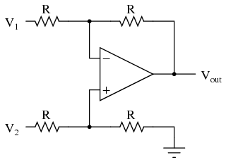
It doesn't always happen. Folks have solved it by putting two separate sensors in one throttle, by using two separate throttles, or it could be solved by adding a difference amplifier at the throttle input to the secondary controller, here is a simple example:
The difference or differential amplifier re-references the output voltage to the ground at the output side. So the grounds moving around with respect to one another don't have any effect on the value the secondary controller sees. I can think of about half a dozen ways to accomplish this.
But there are too many variables to predict exactly how a particular system is going to behave, some real testing is required. Try it and see.
Using tires of different sizes is one way to attempt to bias the system slightly, but some resistors are easier to tune and cheaper, plus they provide more range of adjustment. Controllers don't have exactly the same gain, and motors of the same construction don't have exactly the same Kv due to physical and magnetic variations. Tires wear differently, the rear wears about three times faster than the front, so the bias will change with wear. It also changes with weight distribution and tire pressure.
A better solution is to use torque based throttle controllers. Then a small variation in throttle signals makes a minor torque shift and the system is much less sensitive. Then you can establish a true torque relationship between the two drives by adjusting the controllers, and we again find that PWM throttle based controllers are a liability for good control and performance on our ebikes.
Making an AWD ebike isn't hard. Many people have done it, and many used mismatched components. Perfection is not required. It tends to work best when the system load is higher, then both motors can more easily contribute. When system load is very light one motor can do the whole job and it requires more accurate balance to spread the load, but in that case one motor can do the job anyway, so the second isn't really needed.
Let us know how it works out, it is always interesting to see what problems do (or don't) crop up.