I'm going to turn this into a tutorial thread...
Anytime you spin the axle in the dropouts, the wires can get cut through, or stretched apart. Sometimes a stretched wire will make an intermittant contact, which can blow your controller.
A short in a hall wire can blow the hall sensor inside the motor. Do not try to run a motor that has been spun out before checking all the wires first.
Damaged wires can easily blow you controller!
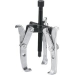
Backing up a step, After you pry the covers off, try to slide the bearing off the axle. Ususally they'll slide right off, but sometimes they're stuck on pretty good. Do not use a hammer or pry against the side of the bearing to avoid denting the dust seal. A gear puller is the best way to get stubborn bearings off.

You can visually inspect the phase wires for damage. If damaged, they can be replaced. If just the insulation is cut, you may be able to slide some heat shrink tubing over the area to protect it.
On the other side, you can access the splices for the hall sensor wires.

Using a sharp blade, you can carefully slit the heat shrink tubing and remove it. From here, you can measure continuity to the connector. With the mini XLR style connector, it is difficult to get a meter probe on the pins, so I used a short piece of solid strand copper wire to back probe the pins on the connector. If you take apart the connector body, you can get to the backside of the pins. You can jam the end of the solid wire into the heatshrink and push it in far enough to make a connection to the pin. From there, the other end of the wire can go to your meter. You need to check for shorts between wires too. This is worse than a broken wire.

To test the individual hall sensors, you need to apply power to the black and red wires.
Something between 5v to 9v will work. You could use a 9v battery if you don't have a power supply. An accidental connection between the +power and the hall signal wire when the output is supposed to be low will destroy the hall sensor, so be careful to insulate the wires from each other.
With +5 going to the hall power wires, you can measure the voltage from each sensor signal wire (the yellow, blue, green wires) to the black wire. With power applied, the output will toggle between high and low when opposite ends of a magnet are put against the sensor. You can use about any small magnet to test with. Strong ones are better.
I measured .02v for a low, and around 3.5v for a high with 5v power.
A dead sensor will be stuck low usually. If the sensor does not toggle when you reverse the magnet, it is bad.
If you locate a bad sensor, you will need to replace it. They are glued in with epoxy. To remove the epoxy, it is very helpful to heat it first. You want to be careful not to overheat and melt anything, but if you get the epoxy up to around 100C, it gets sort of soft and rubbery. Using a very small bladed screwdriver, I dug the epoxy out. Since the old sensor is trashed anyway, it's OK if it gets destroyed in the process. Completely clean out the slot where the sensor sits so the new one will fit.


You can buy new hall sensors from ebikes.ca, Digikey, or a number of other places.
The sensor is a Honeywell SS40A. Digi-Key Part Number 480-1998-ND

Next, I attached the wires from the old sensor onto the new sensor. This is a bit tricky, since you need to keep the solder connection narrow enough so the wires won't touch each other when you place it.

Feed the ends of the wire back through the same slot they came out of and carefully bend the wires so the sensor fits into it's slot. I used a dab of super glue to hold the sensor in place before epoxying it.
View attachment 3
Once the sensor is tacked in, I used a piece of scotch tape over the slot to make sort of a 'dam' to keep the epoxy from running down the face of the stator. With the tape in place, I burried the sensor in epoxy. I used regular 5 min. stuff. The epoxy runs down the sides of the sensor and fills in the dam, then hardens. After the epoxy hardened, I removed the tape.
You could also just let it run down and file off the excess after it gets hard. You want to make sure none of the wires or the sensor will rub against the rotor when you put it back together.

Now about all that's left is to reconnect all the wires. I used a completely new cable for the hall sensors. If the old one is long enough and you cut off the bad part, that would be easier.
I used heat shrink tubing over all the connections. All the black wires go together, and all the red wires go together.

It would be a good idea to re-test the hall sensors before shrinking the heat shrink