"Zephyr" - Finally, the "v4" Fechter/Goodrum/Hecker BMS...

Forgot to mention, it's 30s! So 30*3.65 = 109.5 volts, which is around where I have the charger adjusted based on the shunt leds coming on without cells attached. I thankfully don't have that little of a clue about this stuff! Haha, I don't want to know what would've happened if I tried that... Now the only issue is the first cell's shunt LED (which may be because I jumped the tap wire to the pack negative on the board). I should have a better idea once I charge the pack from a deeper state of discharge (this was practically full already).
 
Odd behavior for the end cell is pretty typical. I call this "end cell effect". The voltage drop in the tap wires gets mostly balanced out for all the cells except the ones on the ends. This results in the end cells getting slightly less due to the voltage drop. Using a heavier wire from the ends of the pack to the board will help.

While it looks strange, the voltage error is quite small and won't hurt the cells. After charge completion, measure the end cells vs. ones in the middle to make sure there isn't some other problem.
 
Zenid said:
I've put together shared project forms that can be used to order the parts.

Zephyr 4.1b LiFePO4 24s components order form:
http://www.mouser.com/ProjectManager/ProjectDetail.aspx?AccessID=7b8daff5cc

Zephyr 4.1b LiPO 24s components order form:

http://www.mouser.com/ProjectManager/ProjectDetail.aspx?AccessID=d4c8fbb68a

The current versions are for 24s, but I will produce 16s versions as time permits (for now, you can just change line items as required). Now we can just update the mouser order form (or shopping cart) to deal with any obsolete parts or substitutions, instead of everybody individually doing their own identical orders. Hopefully this will make things a lot easier.

N.B: This is brand new so PLEASE CHECK before ordering!
yep, you should :D
on RX07 (1kΩ resistor) there is only a quantity of 1... (both versions)

No big deal as I somehow ordered the LifePo4 (RX01 = 48.7kΩ) for my AESC cells...

BTW, what's the formula to calculate RX01 for a desired voltage?
Let's say I prefer 4.0V HVC to prolong the life of my investment, I'm guesstimating 68.1kΩ?

edit: U2, U3: you have only one listed instead of the two required
 
marcexec said:
yep, you should :D
on RX07 (1kΩ resistor) there is only a quantity of 1... (both versions)

No big deal as I somehow ordered the LifePo4 (RX01 = 48.7kΩ) for my AESC cells...

BTW, what's the formula to calculate RX01 for a desired voltage?
Let's say I prefer 4.0V HVC to prolong the life of my investment, I'm guesstimating 68.1kΩ?

edit: U2, U3: only one instead of two
Thanks for the heads-up on the Rx07. I've changed the amount to 24 in the Mouser parts list.
U2/U3 *does* require 2, - one for U2 and one for U3 (same chip). Look on the board.
http://www.zenid.com/images/GF4.1b_L.jpg

As for your query about Rx01, well you know it's 73.2K for LiPO, and 48.7K for LiFePO4, so you can reverse engineer the equation from the respective cell voltages :wink:. Either that or ask Richard. The formula might have been mentioned somewhere earlier in this thread.
 
midwest mayhem said:
Never did this test but finally got everything together and I think it works! Charging a 15Ah LiFePO4 Headway pack with two 54v Meanwell's (max voltage without load is 119 volts). [...]

Below are two videos, one of the beginning of charge and other at the end. In both you can see the issue with the first cell's LED. The only thing different about this cell is I don't have a tap wire, I jumped it to the pack negative like Zenid did. Could this be the issue?

tl;dr I think it works but the first cell LED is wonky.
[Youtube vids]
Thanks to everyone who's been involved in this project! I had no previous experience with this sort of thing (college mechanical engineering student), but was confident with the resources available to me I could figure it out.
Nice work! Great to hear it all came together so well :). Yes, the first cell-circuit is sometimes a teensy bit off, but I've been running mine with my 24s2p pack for over three years without issues.

I saw your build thread: great job! I especially love that crazy custom pack and sheet-metal container - amazing! :D
(http://endless-sphere.com/forums/viewtopic.php?f=6&t=60932)
 
The formula to calculate the voltage is:

VZ= 2.5 (1 + Rx01/Rx02) + .002 x Rx01, where Rxx is expressed in kOhms.

In actual practice, it always seems to be off a little, so it's better to test on a breadboard if you really want to be precise. There is some variation bewteen makers/batches of the 431 chips.
 
fechter said:
The formula to calculate the voltage is:

VZ= 2.5 (1 + Rx01/Rx02) + .002 x Rx01, where Rxx is expressed in kOhms.

In actual practice, it always seems to be off a little, so it's better to test on a breadboard if you really want to be precise. There is some variation bewteen makers/batches of the 431 chips.
That didn't produce good values, RX02 in Ohms works fine, though :)

I ran the formula with a few values.
It's now in the Wiki: http://endless-sphere.com/w/index.php/Zephyr
BTW, I reworked http://endless-sphere.com/w/index.php/BMS_Types as well

Edit: just saw 48.7 yields 4.003V, is that correct?
 
No, I don't think that's right. R2 definitely can't be 120 ohms.
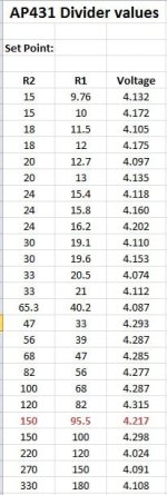
Below is part of a spreadsheet of resistor values; all resistances are in kOhms:
We were trying to dial in what the best values were that were also in stock. High/low range based on accuracy rating of the 431.


AP431 Divider Chart.jpg
Hmm... well doesn't look so good when pasted here. I'll try to do a screen shot later.

Edited Chart.

For the AP431, the formula is 2.495*(1+R1/R2)+(0.0014*R1)
 
Thanks, updated the table in the Wiki, http://endless-sphere.com/w/index.php/Zephyr
spreadsheet attached as well.
 

Attachments

  • Zephyr_HVC.ods
    4.8 KB · Views: 96
marcexec said:
I got that :)
Edited my post to be less ambigous - your BOM has only one, but the board needs at least two.
Thanks, Marc. I see what you mean now: the Mouser order forms BOM, *not* the Word document BOM. I've fixed this in the Mouser order forms accordingly. Thanks for testing that out and reporting the corrections. It should all be plain sailing now for anyone else using the Mouser forms. :)

Zephyr 4.1b LiFePO4 24s components order form: http://www.mouser.com/ProjectManager/ProjectDetail.aspx?AccessID=7b8daff5cc
Zephyr 4.1b LiPO 24s components order form: http://www.mouser.com/ProjectManager/ProjectDetail.aspx?AccessID=d4c8fbb68a
 
Mouser part 283-6.2-RC (Rx04/Rx05 - 6.2Ω) is no longer available unless you buy a ridiculous number, now (1000), so it's been substituted for part 283-10-RC (10Ω) in the order forms (as per Richard's substitution suggestions). If they go back to stocking the 283-6.2-RC in sensible amounts, I'll change it back. [This post edited to a different substitution because of concerns over the case size of another option (660-MOSX3CT631R6R8J)].
 
Thanks for the compliments Zenid! I thought I had this thing working but after a small discharge for a test ride it wouldn't charge again (all cells were 3.35 volts but cell one was 2.8 and nothing was charging). I took it off the bike and was going to replace the balance wire going to cell one (I just jumped to pack minus on the PCB) to see if that would change but then I spotted this:


Notice the break in the PCB trace from the top of the cell 1 circuit going to the header which connects to the top of cell one (bottom of cell two). The diodes across cell circuits one and two read funny on the multimeter and I think are blown, plus the diode over cell circuit two is visibly blown it looks like and the solder pads are burnt.

Do I need to repair the trace and replace the diodes? What could've caused this?
 
Test the diode that goes across that cell circuit. If you're lucky, it's still good. The diode is there as protection for the rest of the cell circuit and may fail shorted. If the diode shorts, it will take out the trace (that was actually intentional by design). Fuses were considered, but too expensive. If the diode shorted, you should be able to replace it and bridge the blown trace on the board.

My guess is the balance wires got swapped around at some point and one circuit got reversed. Check both adjacent cell circuits as well. One of the adjacent cell circuits may have seen double voltage. You could double check voltages at the connector cell by cell to make sure they're all in the right order.

There of course are other possible causes, but something shorted to burn the trace.
 
Cell circuits one and two read zero ohms instead of the usual 169K... Both cell circuits one and two were giving funny readings on the diode test described in the manual. I removed the zener over the second circuit and it tests fine by itself, which makes me think the diode over circuit one must be fine as well, and something else is the issue.

If the cell circuit resistance is zero over both cell circuits then there has to be a short somewhere else on the board right? The BMS is fully disconnected from the battery. I don't believe I made an error in soldering because I thoroughly checked all the circuits before operating the BMS and it fully charged the batteries before.

I can't detect a short between anything and the enclosure. I'm afraid I might damage some components if I slide the PCB out of the case to look at the bottom because it's an incredibly tight fit. I can't see anything out of the ordinary on the top.

Any suggestions to test or possible culprits?
 
Testing is best done with a current limited bench supply applied to the single cell circuit (3.65v).
If you don't have something like this, then a 5v supply and series resistor of something like 100 ohms or a small light bulb to limit the current might work.

About the only part other than the diode that can short and give a zero ohm reading would be the TC54. You could try desoldering it and see if that clears the short. Pretty much everything else has a resistor in series with it.

The cave man approach is to pump in about 1v and 5 amps and see which part starts smoking.
 
Other proven methods to blow a circuit are static electricity and making the pack connection with the charger attached.
 
I did use the diode check function on the meter, it checked out relatively fine once removed from the circuit (almost the same readings as the two extra unused zener's I still had). I guess I'll try the TC54's. If I hook it up to 3.65v CC limited power supply, what do I look for or check next? My understanding of the circuitry is limited at best; I am a mechanical engineering student.

I hesitate to think it was incorrect wiring because the BMS worked before. It balanced the pack using its different methods and shut off at the desired voltage according to the EOC and gave the green light. Every cell was the same voltage to the hundredth of a volt. Then, after moving the bike around a bit and connecting/unconnecting the balance leads (with charger and pack plus/minus unconnected every time), it wouldn't charge correctly anymore and I found this issue.
 
there is one cell that is now totally discharged it appears. it was fully charged before you swapped the balancing plugs around from your comments. that should narrow the focus of what could have happened.
 
If the cell circuit reads shorted with a meter, no use in applying power yet.

I'd try lifting the TC54 first and measuring across the circuit again.

If that doesn't clear the short, next would be to lift the two big shunt resistors (you can unsolder one end of each and lift them to break the circuit. If this clears the short then the BD136 transistor blew.
 
fechter said:
I'd try lifting the TC54 first and measuring across the circuit again.
This did the trick - the TC54's were causing the short in both of the cell circuits. Replaced them and the diode over the 2nd circuit for good measure - everything checks out normal with the multimeter now.

Now, the issue is how do I avoid this happening again if I don't know what caused it? Could not having all the balance wires connected at the same time be an issue? I don't use a tap wire to the cell 1 negative; I jumped it to the pack negative cable. After testing the charging cycle a few times, I would disconnect the pack negative cable, which would leave every cell connected to the balance section except the bottom of cell one.

Should I always leave the pack negative cable connected (so every cell is fully connected to balance section)? If I wanted to have the BMS "switched," can I install a switch inline with the pack positive cable? The top of the most positive cell has it's own tap wire. I would like to isolate the battery as fully as possible in between rides and charges.

I managed to slide the board out and it was very apparent which components got hot. I was surprised there wasn't more evidence of heat around the failed TC54's.


The culprits:

 
The diodes are supposed to protect the TC54s against overvoltage when making connections. Perhaps the diodes are not clamping at a low enough voltage (but they definitely should be according to the data sheet).

I would recommend adding a wire so the pack negative is always connected to the board. On mine, I use a big Molex plug for the tap wires and a separate 2 conductor Anderson plug for the main pack connections. This allows removal of the board. When connecting the board, I make the main pack connection first, then plug in the tap wires.

It's hard to say exactly what caused the failure. The TC54 must have seen over 12v at some point, or possibly they were just defectively manufactured. Static electricity can easily kill them also when handling the board. As long as the board stays connected to the pack, they should be bulletproof.

The only other failures I've seen in the past were caused by making pack to board connections while the charger was connected, which caused a big spike when the pack charged the output capacitors in the charger.
 
Got everything hooked up again and I'm running into the same issue - the pack doesn't seem to be charging and then first two shunt LED's are lit up, even though the first cell is at 2.85 volts and the other 29 are all at 3.34 volts. Last time this happened I just let it go figuring it would work itself out but that's when I melted the trace. After disconnecting everything the cell circuits still read 169kOhms of resistance, so thankfully nothing blew.

This is confusing to me because the first time I used it it worked fine, balanced everything, charged it up till the green light then shut off. Now it's stuck with the yellow light and first two shunt LED's slowly bleeding the first cell.


Any ideas?
 
When the shunt LEDs are lit, the circuit thinks they're too high and cuts the charging current.
If it's lighting up with only 2.85v, there's a problem. Try holding the board up to a light and backlight it so you see the traces as shadows. Inspect closely the suspect cell circuits and look for solder bridges. I've done this a few times and they can be hard to spot.

Ideally you'd want to test the cell circuit independently with a current limited power supply. If you measure a few spots, it may be possible to narrow down things. If the shunt is on, basically either the 431 is getting a wrong signal, is defective or the BD136 is blown. Measuring the reference pin (pin 1) against the negative cell connection should show 2.5v when the shunt is active. If you lift one leg of the R101 top divider resistor, the shunt should definitely be off.

Double check the R101, R102 divider resistors with an ohmmeter to make sure they have the right values (power off).
 
Back
Top