Yet another Lebowski + Honda IMA inverter & step-by-step

marcexec

1 kW
Joined
Mar 10, 2009
Messages
434
Location
Dublin, Ireland

Intro:​


kiwifiat challenged me with a SMD Lebowski board (thanks for the trust & funding from coleeasterling as well!) to integrate into the Honda IMA inverter and test on my motorbike as I have the Enertrac MHM 10kW hub motor and run 36S Nissan Leaf modules, so plenty to play with.
Here's the lovely board, modified for Hall sensors:20230519_083712.jpg
and my inverter, fresh from Florida:20230519_083727.jpg
The CAT5 patch cable will be sacrificed for connections. Note it's highly recommended to use shielded cable, this one wasn't...
Unfortunately the case got damaged a bit during shipping :(20230519_084002.jpg
Scope is to get the hub motor with hall sensors spinning and usable as the bike is daily'ed by me and document the process in detail.
Note that the board is designed to be used with a resolver, mine was "downgraded" by Roger for my motor.
 
Last edited:

Let's get started!​

1) Disassembly of the Honda IMA Inverter​

(part numbers start with 1B100-RMX or 1B300-RMX, no difference has been found yet):
You will need:
  • small 10mm socket (e.g. 3/8 drive, not 1/2 - it wouldn't fit the two bolts between the phase connections)
  • Philips screwdriver
remove the two plastic Philips screw's then pull the clips out by the ring:Philips.png
you can now access the 10mm bolts
20230519_084504.jpg
they will need a bit of force at first but are then easy to remove
20230519_084631.jpg
the 4 longer cover bolts will be similar
20230519_084737.jpg
That's it, disassembly done!
 
Last edited:

Intro:

kiwifiat challenged me with a SMD Lebowski board (thanks for the trust!) to integrate into the Honda IMA inverter and test on my motorbike as I have the Enertrac MHM 10kW hub motor and run 36S Nissan Leaf modules, so plenty to play with.
Here's the lovely board, modified for Hall sensors:
and my inverter, fresh from Florida:
The CAT5 patch cable will be sacrificed for connections.
Unfortunately the case got damaged a bit during shipping :(
You can mostly thank Coleasterling for the board, he not only pushed this project along but also paid for your board. It is a shame the inverter got damaged. A few of the inverters Eric Ensley sent me got badly smashed, one was basically pulverized with the cover broken into many pieces, components dislodged and the most important chip on the pcb having a fracture.right through the middle of it.

Looking forward to seeing this project progress.
 
If it's helpful, I have some info on doing this over here, though I have yet to finish the last wiring steps and get it working. :(


2) Outside work with acetone and heat gun​


The goal is to remove the conformal coating from the contacts of the PCB that we have to solder to later and also remove/desolder unneeded components.
You will need:
  • Acetone (note not all nail polish remover is proper acetone nowadays, check the ingredients!)
  • a well ventilated space
  • protection for your work surface
  • old clothing in case you splash yourself
  • (disposable) gloves
  • mask if you get headaches from solvents
  • brush or cotton buds ("q-tips")
20230521_192621.jpg

For the desoldering add:
  • heat gun
  • small pliers
  • tweezers or a flathead screwdriver
setup:
20230521_193742.jpg
Before we start, keep in mind that the acetone will liquify the conformal coating. You will have to move it away from the solder joints and/or dab it up while dissolved. It will re-harden somewhat once the acetone has evaporated. I did both - brushed it away and dabbed some up with a cloth.

As you can see I have marked the tasks with tape - red and white are components to be desoldered, blue is for the acetone.
See next picture as well.

For the desoldering use the heat gun on the lower setting (650℃ on mine) and try to evenly heat the area around the component. The MCU is probably hardest. I gently lifted one corner up after about 30-40 seconds heating, but still lifted some traces. Make sure you don't create any shorts. Use the pliers to move the hot components away.

20230521_194445.jpg
(ignore the standoffs for now, I trialled a selection)
Repeat with the 6 capacitors marked in red and white. I thought the lower ones were optional (they are not) but it's so easy you can just keep plucking them off.
The result:
20230521_195541.jpg
(yes, I found and binned the last capacitor immediately afterwards)
 
Last edited:

3) Mechanically mounting the Lebowski board​

You will need:
  • wire cutter or small saw
  • a file
  • 5x 5mm high standoffs e.g. from ATX mainboards plus fitting screws
    alternatively longer plastic screws with a flat head and 4-5mm spacers, plastic is fine
  • precision wire cutter/snips, angle grinder with sanding disk and/or rotary tool ("Dremel")
With the capacitors out of the way only the 3 black plastic "pins" close to the three phase connections remain. I just snipped them off below the tip and filed them off somewhat.
black pins.jpg
I didn't have enough standoffs of the same type at hand so I just cut and drilled some 4mm PET sheet that I had handy along with fitting flathead plastic screws.
20230524_104633.jpg
With the bottom half sorted, we now need to modify the plastic cover with the big capacitors. Have a look at the indentations in the play-doh from the ridges in the cover to see why.
indentations.png
We'll remove these to make space for the Lebowski board. I started with snippers as they have the right angle. Eventually I moved to the angle grinder with a flap disc to deburr and sand off an extra mm in some places. It's more effective, but much messier. Note the plastic is rather brittle.20230521_203111.jpg20230522_094508.jpg
Done, the cover should now fit with the board in place. Don't forget to remove any overhangs (because of melting) and clean the cover.20230522_095340.jpg
 
Last edited:

4) "External" (to outside connectors) wiring​

You will need:
  • soldering iron & solder
  • flexible wiring, twisted pairs for signals, so a CAT5e or 6 shielded (F/UTP, S/FTP) patch cable is ideal. Note that you have to be careful not to overheat as the insulation retracts faster than e.g. automotive cable. Note the pictures show unshielded cable which might be creating an issue with some signals.
  • hot glue to keep the wiring neat under the board (optional)
Connection overview:
  • Throttles
  • Halls (different if you use resolver or sensorless of course)
  • Serial
  • Jumpers Pushbuttons (Reset & Set)
  • Temperature sensors (optional)
  • board "12V" connections (the board can actually take up to 30V, not sure about the inverter itself, the caps are rated to 35V though)
Sanity check:
First of all we power the board up carefully (current limited, e.g lab power supply) through the 12V connector on the top right. Limit to ~500mA and bring the voltage up from 7V. The 5V LED should light up. Measure 5V output e.g. on the throttle or temp sensor pads, it should be 5.15V-5.25V.

Prepare wires (assuming exit near the existing grey CN3 outside connector):
Without the temp sensors, but with dedicated grounds you will need 17 wires, so I roughly halved my patch (leave about 15cm for internal wiring) cable and added a single black wire. Remove the outer sleeve so that you have 10-20mm to the left of the board when holding the wires to the furthest points to the right.
Strip and tin the longest ones now to save yourself some pain. If your wire stripper rips the insulation off like mine, stick with the "roll over blade" method.
The first patch cable half goes to the top & right of the board - no harm in matching my colour choice:

Cable #1 - Halls:
US4Brown
VS2Brown/White
WS1Green/White
+5V [Halls]+CSPOrange
Ground [Halls]-CSPOrange/White

Cable #1 - Serial:
RxBlue/White
TxBlue
Ground [Serial]Green


Cable #2 - Setup and Reset buttons:
Set +Blue
Set -Blue/White
Reset +Green
Reset -Green/White


Cable #2 - Throttles

Ground [Throttles]GNDBlack (separate)
Reverse (connect to +5V to enable)REVOrange/White
Throttle 1TH1Brown
Throttle 2TH2Brown/White
+5V [Throttles]+5VOrange

To solder mount the board into a holder or a 3rd hand so you can push the wires through from the bottom and solder at the top. Start with the longest ones and snip off the slack of the short ones as you work from right to left:
20230609_085852.jpg
Double-check that the wires are even and flat against the PCB and the solder has flowed properly:
20230609_090002.jpg
If the sleeved part is short enough (~40cm for me) you can pull individual pairs to straighten the underside.
I used some hot glue to keep it nice and even:
20230610_163017.jpg
 
Last edited:

5) "Internal" (to the inverter's PCB) wiring (part 1)​

You will need:
  • soldering iron & solder
  • flexible wiring:
    • ~15cm of leftovers from the patch cable should suffice for gate and current sensor connections
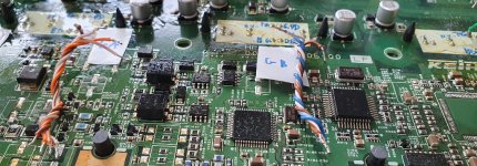
    • 2x ~13cm for the "remote" GND1 & +16V connections (blue/black & orange/yellow in my pictures)
    • 8 and 5cm for HV Battery + and - respectively. The former needs a 6mm ring terminal.
    • 20cm plus outside length for 12V power (red/white & black here))
  • something to label the connections - I used white tape & a DVD marker
  • multimeter
With the existing components in the way it helps to plan a little, here are the 6 stages:
  1. label everything
  2. solder the "remote" wires to the Lebowski board
  3. prepare the 3 gate wiring "trees" and solder them to the inverter PCB
  4. solder gate wiring to the Lebowski board
  5. prepare the current sensor pairs, solder them to the Lebowski board, pull it down and solder them to the inverter PCB
  6. attach the other ends of the remote wires to the inverter PCB
1. Labelling
Pay special attention to the gate drivers. Previous guides have top (upper) gate and bottom gate swapped. This works e.g. for the OpenInverter board, but not Lebowski. I went a bit overboard for illustrative purposes as the gate and sensor pins line up anyway with the connectors on this specific Lebowski board, which makes it so awesome! :)
20230610_160307 all.jpg
Closeup of the gate driver(A) with the 4 pins labelled:
20230610_160307.jpg
Again, GLA, GLB and GLC go to pin 8 from the various guides, GHA, GHB and GHC go to pin 6. Here's the pinout from the PDFs:
Screenshot 2023-06-13 15.26.56.png
We'll use the HV-, pin 4 from Gate A only.

2. Attach the "remote" wires
Attach the wires to the board (first column), not the inverter PCB yet.

VPackHV Battery +Red (6mm ring terminal)8cm
+16VCapacitor next to transformerRed/Yellow13cm
GND1Capacitor next to transformerBlue/Black13cm
R57 & R33HV- from Gate A pin 4black4-5cm
+12V+ LV DC & externalred/white20cm plus exernal
-12V- LV DC & externalblack20cm plus exernal
20230611_155803 remote.jpg

3. Prepare the 3 gate wiring "trees" and solder them to the inverter PCB

These will be the trickiest part. For the next step keep in mind that the 4 wires for each gate driver will have to be soldered into the board from the bottom, so look at the order of the wires and hold that end of the "trees" flat and at an even length with one hand as you twist and bend the 4 wires. They should be around 5cm long.

Note the order is not the same for all three (at least in this revision), Desat is first for gate B, but ground, lower and upper (high side) order stays the same:
GND - GLA - GUA - Desat | Desat - GND - GLB - GUB | GND - GLC - GUC - Desat
Cut, strip and tin the 4 wires. Next hold one end as above and twist the rest, then bend the other ends in the 4 directions:
20230610_160246.jpg
Next, solder them to the 4 pins of the PCB as labelled in 1). We're doing this first as the mounted board will partially cover the pins. I fed the wires from the bottom:
20230611_104901.jpg
20230611_151506 remote.jpg
4. solder gate wiring to the Lebowski board
This is straightforward thank to the preparation. Start on the left if you're right-handed.
20230611_105346.jpg
A good 3rd hand to hold the board is extremely helpful.
20230611_105548.jpg
Double-check your wiring, e.g. with the continuity setting on your multimeter.

(continued in the next post due to attachment limitation)
 

Attachments

  • 20230611_104222.jpg
    20230611_104222.jpg
    574.6 KB · Views: 5
Last edited:

5) "Internal" (to the inverter's PCB) wiring (part 2)​


5. current sensor wiring
I used the same colours as on the respective gates. Wires are 3-4cm long. Solder them to the board, bend it down and solder the other end to the PCB. Ground is the middle one.
20230611_151506.jpg
Screw the board down and check all the connections again.

6. Attaching remote wires
Solder HV- to the pin on gate A, then stick the ring terminal for HV+ between the bar and the nut on the first/top left connection. You might have to file down the left&right edges of the ring terminal.
Then solder GND1 and +16V to the capacitor in the top middle (left in the picture). Route them nicely between components so the aren't in the way. Hot glue is optional.
Lastly strip, tin and solder -12V then +12V to the two pads above the grey connector. I opted to have only one set of wires as both boards have to be powered at he same time.
20230611_155803.jpg
Congrats if you made it this far, the hardest part is done.
 
Last edited:

6) Basic testing / sanity checks​

You will need:
  • serial cable or USB-to-Serial converter (e.g. CH340) and appropriate cables
  • current limited, adjustable power supply
  • multimeter
  • Serial terminal device
    • Windows PC or laptop use Termite
    • Linux or Chromebook with Debian VM use GTKterm
Power checks:
  • Power 12V from the power supply, limit current to 0.5A. Carefully bring the voltage up from 5-12V. Stop and check for shorts if the current is too high and voltage gets pulled down. Expected draw is <400mA at 12.50V
  • The 5V LED will light up. Measure the 5V output e.g. at the temperature sensors. You should get between 5.150 and 5.250V, which are required for a stable power supply.
  • Measure GND1 & +16V
  • Measure voltage on the the 3 Desat connections. If it's not ~5V on all of them the chip is held in reset (safety feature).
Setup mode:
  • remove 12V power
  • check RES (Reset) is not shorted
  • short/jumper the SET (Setup) wires - blue and blue/white
  • enable 12V power again
  • the Drive_0 - Drive_3 LEDs should flash now, if not, check everything above
Serial communication:
If you haven't already, now it's time to have a look at the Lebowski manual - https://endless-sphere.com/sphere/attachments/user_manual_v2pa1-pdf.223095/
  • connect the serial cable/converter, note that TX on the board goes to RX on your device and vice versa
  • Open Termite or GTKterm on 115200, 8 data bits, 1 Stop bit, no Parity or Flow control2023-06-19 21_02_03-Termite 3.1 (by CompuPhase).png
  • you should see the config menu
TOG success.jpeg
 
Last edited:
Nice progress, with the IMA inverter make sure you set menu K sub-item m) to disable. Also in menu N set sub-item c) to disable. If you would like me to run through the initial setup via remote desktop let me know.
 

7) Closing the box & external connections​

You will need:
  • small 10mm socket (e.g. 3/8 drive, not 1/2 - it wouldn't fit the two bolts between the phase connections)
  • Philips screwdriver
  • drill / step drill
  • grommet or cable gland and epoxy
  • cable ties, small enclosure or junction box, switch or jumper pins [optional]
  • your preferred connectors plus matching crimper
  • soldering iron & heat shink
This will heavily depend on your install location, environmental factors, existing parts and wiring etc. so I'm treating this as an example only. I chose to use a cable gland and external junction box.
The modification is straightforward, drill a hole in the cover "above" the grey connector and epoxy the gland's thread in as it didn't come with a nut. Interior space is limited so I cut the bottom part off as well.
20230611_202828.jpg
Be smart and put some tape on the threads if you're using epoxy and intend putting the cover upside down.
20230611_202834.jpg
I fed the wires into and through a junction box to keep the CH340 and jumpers dry and tidy. Again, push buttons close to where you operate (e.g. handlebar) will greatly speed up every config iteration.20230629_114715.jpg
I used Tyco SuperSeal knockoffs for throttle and halls as I already have them on the bike. Adding red tape to the right connector (marked "P") for + HVDC is also a good idea.

Update:
Post initial testing on the bike and getting FOC working I took the controller out again and sealed up the seams with aluminium tape.
Even with that, the enclosure is not waterproof. However, with the phase connections on top and covered with a splash shield to prevent water pooling on top ("under" the phase connection terminals) this should prove fine.
20230721_093505.jpg
I also added aluminium tape to the wires (remember to use shielded wires or braiding from the start!) and the remaining connections:20230721_093430.jpg
Connection concept in this example:
  • 12V is provided by the DC/DC converter via one relay
  • the second relay is to switch ground (red/black) for Throttle 2 for variable regen when the rear brake engages (via diode) - three pin connector to the "vehicle side"
  • +5V (orange) is looped and ends in the 2 pin connector that will go to the 5 switch handlebar mount for reverse
  • two further buttons are used for reset (RES) and setup (SET), this is highly recommended to save time during the tuning process
 
Last edited:
[WIP, but safe to use]
8) Inverter/controller overview & configuration example
You will need:
  • Serial terminal device
    • Windows PC or laptop use Termite
    • Linux or Chromebook with Debian VM use GTKterm
  • Working throttle must be connected
  • pushbuttons connected to Reset and Setup
Some basic specs and parameters from my research in this forum, happy to correct if I get anything wrong:
  • current sensor transimpedance is 5.8mV/A, they are capable of 350A phase, measurements across the +/- 2V range actually indicate ~6.1mV/A, which gets us 328A phase.
  • Max voltage is ~200V, above that clipping can become a problem, however much higher voltage could be possible (not that I recommend it!)
  • IGBTs can be run at 7kHz, deadtime is 2500ns, gate drivers are active high
  • connector threads are M8
  • mounting holes are ~9mm
Before changing any of the settings, re-read the manual. Use any settings with a metric ton of salt and be sure to use fuses etc.

I have 18 Gen 1 Leaf modules (36S), so around 130V nominal & 150V max.

My example is based on the (rather rare) Enertrac MHM602 (spec sheet attached below), which is a 12 pole pair, 30kW peak hub motor. Measured at 145V, 150A and 10k-eRPM is L) inductance: 119.68 uH & R) resistance: 36.87 mOhm

General tuning tips are in the next post.

For you own sanity, enable the logging in the serial terminal each time so you can review changes and spot trends. For the latter it helps to track changes in a spreadsheet, here is mine: Lebowski settings tracker RF400e
Gamer's advice applies: save early, save often! Once you have a working setup or even an improvement, use option b in Menu Z (print data in HEX format) to export good configs.

This is the menu as seen in the terminal, some options might look different depending on the firmware version.
Note: I will refer to the Main Menu items with Capital letters and sub-menu selections with lowercase

Code:
########################################
#   (c)opyright 2020, B.M. Putter      #
#   Adliswil, Switzerland              #
#   bmp72@hotmail.com                  #
#                                      #
#  version 2.B0                        #
#  experimental, use at your own risk  #
########################################


0) mode: Hall sensored
a) PWM parameters
b) current settings
c) throttle setup
d) erpm limits
e) battery
f) current sensor calibration
g) control loop coefficients
h) filter bandwidths
i) FOC motor impedance
j) CAN setup
k) recovery
l) hall sensored only
m) temperature sensors
n) miscellaneous
o) online Kv, L and R
y) chip status at last drive_1
z) store parameters in ROM for motor use

Basic configuration

Do not connect the high voltage (HV) battery yet, 12V only!
Put the controller in setup mode and connect serial.

  1. 0 - to toggle to Hall mode
  2. A - PWM
    1. a - 7
    2. b - 2500
    3. d & e - toggle to active high
    4. g - autocomplete
    5. z - return
  3. Z - store parameters
    1. a - save
    2. z - return
Reset and reconnect. Check if the settings are saved. If so, turn off and connect the HV battery in a safe manner.
Supply 12V again and reconnect serial. Make sure the vehicle is safe as the motor is able to spin now!

The general principle is that you change settings in alphabetical order and use autocomplete to get a working base setup. This is a must when you change anything in Menu A! (some variables are derived and change immediately without going into the menu entries...)
 

Attachments

  • Enertrac MHM602 - productspecs.pdf
    91.7 KB · Views: 10
Last edited:
9) FAQ, tuning tips, snippets and educational face palms lessons learned

Input welcome!

FAQ
  • f_sample as mention in threads and documentation is h) loop sample frequency: in menu A, and should be at least 24kHz for good operation.
  • Drive modes are as follows:
    • Drive_0 - startup/enabled
    • Drive_1 - Recovery (after errors)
    • Drive_2 - Sensored (e.g. Halls)
    • Drive_3 - FOC operation
Tuning tips
  • hall sensor calibration is done without load, but the subsequent tuning best done under load (i.e. driving). To save the collected data (Hall sensor stats as displayed in L\#) you must enter Setup mode after a (test) run! The data is lost if you just turn the controller off. Thus the recommendation for a button mounted on the handlebar/dash.
  • if the jump from Drive_2 (Hall) to Drive_3 (FOC) fails or is rough, the first step is to increase the transition eRPM (D\f) temporarily to give you a bigger window to tune Halls first. The transition can then be smoothed further by giving the controller a bigger "window" through an increased (H\b) (dr2: speed filter 50% step response time [ms]). I went from 50 (Hall default) to 225, note 200 is the default under sensorless start.
  • "Conking out" (i.e. fallback to Drive_1 due to e.g. an overcurrent error) in Drive_2 after increasing phase amps can be partially addressed by autocompleting on higher phase amps, which calculates a higher B\G value and then dropping down again.
    This reduces your margins of error! See my build tread as well.

Snippets
  • [kiwifiat] The Honda IMA has ~350A current sensors and I find they have quite large and irregular offsets so I now set sub menu m) in menu b) which is current sensor offset filtering to say 10A. I zero the current sensor calibration in menu f) then run the motor for a while and let the controller collect some stats on the sensor offsets while the motor is actually running. Once that is done I set sub menu m) in b) back to zero and run with that. You can enter menu f) and see what the controller has set the offsets to.
    (as below, only B\m set to 10 is adequate already for the IMA)
  • [lebowski] I typically have c at 150, d around 700 and e around 300 ... But if you notice it jumping around between drive 2 and 3 too much you can increase the numbers. They should be relatively low though.
    -> Translates to settings in D
    Code:
    d) accept direction change below: 150 erpm
    e) erpm dr3 back to dr2: 300 erpm
    f) erpm dr2 jump to dr3: 700 erpm
  • [lebowski] The menus are organised such that when you change something in a certain menu you may have to run all the subsequent ones again. This is mostly true for far-reaching settings as f_sample, the current sensor sensitivity and the max phase current.
  • [arlo1](on startup power) I also proved the current sensor calibration by doing a FOC measurement before and after each time trying to use the most amps possible to get the inductance measurement and with the current sensors calibrated properly it lets me do the FOC at a higher amperage. That combined with how smooth it is at light throttle startups shows me the current sensor calibration is worth it. It just takes a few trys at low current to get it perfect some times.
  • [lebowski] About cutting out of drive 3, maybe increase in the bandwidths menu [H\b,c & d] the error current 50% response time to 5 milli sec. Another thing to try would be to increase the proportional error current setting to 2.4A, its in the current menu option k. It should not cut out, if setup correctly.
  • [lebowski] That it conks out when closing throttle, this can have to do with the inductor calibration, did you calibrate it at the voltage you're running at?

Lessons learned
  • double check that the voltage is set correctly, it can throw off subsequent measurements
  • do not lower eRPM of hall calibration - measurements should be taken cleanly in Drive_3 (FOC): D\f should be lower than L\d
  • you need to save results of hall calibration by going into setup directly without power loss or reset, otherwise you just wasted your time
  • while the boards usually have jumpers, it's best to have momentary switches/push buttons connected to Setup and Reset, the latter ideally accessible during use as runaway situations have happened with some configurations. Opening the contactor under load could cost you your controller.
  • Don't mess with B\m, leave the current sensors zeroed out.
  • Impedance measurement, i.e. inductance (L) and resistance (R) are critical to smooth and efficient FOC operation. They are voltage and current dependent.
  • Hall sensors are somewhat imprecise and it's OK to play with the offset. The collected measurements are a guide but at low eRPM in hub motors they can vary significantly. It's OK to change in steps up to 2 or 3 degrees at first and test in real driving scenarios.
 
Last edited:
Snippets
  • [kiwifiat] The Honda IMA has ~350A current sensors and I find they have quite large and irregular offsets so I now set sub menu m) in menu b) which is current sensor offset filtering to say 10A. I zero the current sensor calibration in menu f) then run the motor for a while and let the controller collect some stats on the sensor offsets while the motor is actually running. Once that is done I set sub menu m) in b) back to zero and run with that. You can enter menu f) and see what the controller has set the offsets to.
Just an update on this topic of current sensor calibration, following past discussions with Lebowski the best option is to autocomplete menu f) and not run the offset calibration. If you do run the offset test repeatedly you will observe that the offsets change which demonstrates the point made by Lebowski elsewhere. If you have significant offsets in the neutral point the best option is to replace the offending sensor.
 
If it's helpful, I have some info on doing this over here, though I have yet to finish the last wiring steps and get it working. :(

Thanks, I've been referring to it regularly. Maybe a little challenge to finish? :)
 
Maybe a little challenge to finish? :)


I'd love to...just that every time I start, something gets in the way (i get sick, or have to work extra hours and get exhausted, etc. I can read and post on ES from my bed between dozings as I rest, or work on my music the same way, so those are things I can often do...but getting up and going to the workstation and focusing on a task that will probably result in damage I can't fix if I mess up...eventually I'll get back to it. :( ).

In the meantime I've been saving this thread locally everytime you post to it. :)
Agreed, the fiddly bits are best done with plenty of time and no distractions, though Roger's board fits nicely and is well labelled.
However, once you have it put together, it will forgive small mistakes in the config. Items with potential for grave errors are clearly called out above.

And thanks, that's high praise coming from you :)
 
I have what seems to be a much smaller older version of the brain from Kiwifiat, that fits easily into the IMA module case without even modifying the case, IIRC. Not sure if there is still a pic of it in my thread since images have gone missing over the last several years from server problems.

EDIT: I found two pictures as a size comparison:
1689354873089.png

1689354886411.png

And an image from Kiwifiat with a bare PCB on the IMA board:
1689355000403.png
 
Last edited:
10) Experimenting with throttle curves of Lebowski's polinomal throttle calc

A good graphing site is Graph Plotter

Single throttle with a bit of regen under ~38% (untested)
y= -0.9x + 2.7 x^2 - 0.8 x^3

Screenshot 2023-07-17 12.40.00.png

Not sure how useful this is, likely throttle two to be triggered by the brake on signal & a relay is more practical, bar a second throttle for variable regen of course.
 
Last edited:
Not sure how useful this is, likely throttle two to be triggered by the brake on signal & a relay is more practical, bar a second throttle for variable regen of course.
My plan for SB Cruiser was to use throttle two as a regen control operated by a cable-operated throttle pulled by the brake lever.

Throttle one would just use the output from the CA's throttle (since I use the CA to interpret a throttle and PAS to make a throttle output).

I can't recall if there's a setting to make the brain disregard one throttle input when the other is active, but if not then I'd just use a switch on the brake lever to cut the CA output to the brain.


I'm already using things almost this way with the present pair of controllers; they don't have separate regen inputs but one of them supports the GrinTech method of throttle voltage = 0-0.8v = variable regen, which the CA will automatically do when the ebrake signal is active, taking the throttle input and varying output between those voltages instead of the normal range.

So the COT-brake lever setup has three relays wired to the switch. 1 switches the CA's throttle input between brake COT and throttle COT. 2 engages the CA ebrake input. 3 turns on the brake lights.


Only change of wiring from that to LB/HI controllers would be relay 1 out of picture, brake-COT directly to the LB/HI brake (throttle2) input. Potentially leave relay1 to cut off throttle-COT from LB/HI throttle1 input.
 
Last edited:
Interesting thread... will be watching with eager anticipation. ;)

Have lots of questions but am thinking those will be answered when road testing begins...

Good work!
 
Have lots of questions but am thinking those will be answered when road testing begins...
What kind of questions, generally?
 
Mostly with the SPec's of the Honda IMA....
From what I can find (not all-inclusive) the inverter is rated for a 10kw "assist" motor.... to me that means intermittent duty; whereas, in the bike it will be continuous duty with the MH602 (10k/30k peak)... ?? IDK...seems like the IMA is underrated for the Enertrac motor??
 
Back
Top