
You are using an out of date browser. It may not display this or other websites correctly.
You should upgrade or use an alternative browser.
You should upgrade or use an alternative browser.
"Zephyr" - Finally, the "v4" Fechter/Goodrum/Hecker BMS...
- Thread starter GGoodrum
- Start date
Funny how ES seems to show up in a lot of my searches too. We're almost famous here.
My latest thought is to graft a MAX11081 to a new version of the shunt circuit.
The old 431 based shunts draw close to 400uA on standby when the cells are near full. This drops to about 200uA by the time they approach LVC, so average around 300uA.
The new circuit will drain more like 10uA on standby, and operates in switching mode so the transistor doesn't dissipate much heat. It's bad enough to dissipate all the heat from shunt resistors, so if the transistors don't get hot, that makes heat sinking much easier.
Since the MAX11081 already has the 'any' logic built in, we can use that and add a chain of opto couplers to detect the 'all' condition and terminate charge. Optos suck for LVC since they draw so much. MAX takes care of that. During charge, power consumption is not an issue, so cheap optos will work fine. 12s boards can be concentrated to one opto to get chained to other boards. This should be fine for up to about 240s cells. For less than 12, a jumper needs to be added.
The charge control/LVC interface should be separate. 12s cell boards with shunts could then be added.
There are still a few issues with the new shunt circuit, but initial testing is promising. I don't know what the parts count will look like yet, but for sure much less than previous designs. Much smaller too, depending on shunt current.
I can do a 8s version for Boeing.
SlyCayer
100 W
I can't wait for you guys to complete this, I am eager to build one.
methods
1 GW
I have the opto's I am using working at less than 100uA. Those are about $0.33 each. There is another flavor that will work down near 10uA but they are more like a buck each.
Hey - you know that those detectors that you pointed me to for my design are now for sale @ sub 3,000pcs right? They can now be had in small batches depending on availability. My method is to truncate the part number and feed it into OctoPart. This brings up every flavor ordered from cheapest/most available. Then I take the part number and cross-reference the setting points - there are a few that might work for what you are doing.
Maxim chip is probably a better route.
If you need I can spin a tiny piggy-back board that converts it to DIP :wink:
-methods
bigmoose
1 MW
I liked the MAX11081 too:  wished the LVC range extended up a few tenths of volts more though.
.jpg")
.jpg")
wished the LVC range extended up a few tenths of volts more though. bigmoose said:I liked the MAX11081 too:
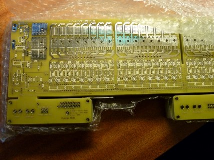
Where are those boards from?
It seems like all the commercial chips have a pretty low LVC. If you're using kind of saggy cells, that might be OK as the voltage will bounce back when the load drops. Even with stout cells, I don't think it would hurt them. You should avoid running the pack that low anyway and a pack level LVC set higher could be the primary cutoff.
Mouser shows them for $8.67 in singles and $4.08 for 100. For 12 cells, that's pretty cheap. They also have them in stock.
The only chip I like better is the Seiko S-8209 that has balancing, but those seem to be by factory order only and are not programmable. You have to order them with the set points you want.
The new shunt design is based on the TC54 that I used for LVC on the older boards. I had some around so used them, but there may be other similar chips that are cheaper.
MattyCiii
100 kW
Gawd I wish I could find the link - but I read an article awhile back aimed at small entrepreneurs on how to price things. Most small businesses sell things below a sustainable cost, and pay the price. IIRC you should be charging at least 2.7 * the nominal cost of parts & labor.methods said:... I do have them over-priced - hence why I am searching the internet for that maxim protection chip. :wink:
-methods
I'd rather pay more, and know MethTek.com will be there when I want more - than get a dirt cheap price on someone who has to quit the biz a few months later because they ain't paying the bills. Same is true foe GGoodrum & Fechter products.
The higher price will likely mean fewer sales... but that works for Tesla, and Recumpense.
bigmoose
1 MW
fechter said:Where are those boards from?
That was a board I rolled last year around fall.
Hi,
after long time on the shelf, i soldered a 16s Zephyr 4.4.2, but the cell circuit test shows 3 Ohms at circuit number 8 and 16. I changed nearly all parts, checked everything twice but could not figure out any mistake. Does anybody have an idea what could be wrong. Stange that it is on 8 and 16.
Thanks in advance.
Martin
mj2412 said:Hi,
after long time on the shelf, i soldered a 16s Zephyr 4.4.2, but the cell circuit test shows 3 Ohms at circuit number 8 and 16. I changed nearly all parts, checked everything twice but could not figure out any mistake. Does anybody have an idea what could be wrong. Stange that it is on 8 and 16.
Thanks in advance.
Martin
There is a mistake in the board layout. The emitter and collector of the transistors are shorted by a through hole. The trace needs to be cut and rerouted so it doesn't connect to the big hole. You can use a dremel grinder or sharp blade to cut the trace on either side of the hole, then use a small piece of wire to bridge around it.
There may be other issues with that layout, I'll try to take a look. I see I have revisions to the schematic but it's hard to tell if they are reflected in the layout.

Below is the corrected schematic. There was a diode (D9) added from Q2 to U3 pin 7. Try to check your board to see if this exists. If not, it should be added. Click on the picture to enlarge.
Sorry, those are unobtainium these days. I'm still looking for a more cost-effective solution.
joe tomten
100 W
I have one of the V4. unopened board available if someone wants it.
Zenid
100 W
FYI. The latest "Zephyr" v4.4a is in stock now
http://endless-sphere.com/forums/viewtopic.php?f=31&t=55125
Buy one and help the designers breathe life back into this great project!
http://endless-sphere.com/forums/viewtopic.php?f=31&t=55125
Buy one and help the designers breathe life back into this great project!
cal3thousand
10 MW
Zenid said:FYI. The latest "Zephyr" v4.4a is in stock now
http://endless-sphere.com/forums/viewtopic.php?f=31&t=55125
Buy one and help the designers breathe life back into this great project!
Are there any working iterations out in the wild yet? Besides Fechters and GGoodrums
Zenid
100 W
Yes! Here:cal3thousand said:Are there any working iterations out in the wild yet? Besides Fechters and GGoodrums
Blog Guide(1): Building the “Zephyr” BMS Circuit Board
http://zenid10.wordpress.com/2011/08/28/building-the-zephyr-circuit-board/
Blog Guide(2): Wiring and assembling the Zephyr BMS
http://zenid10.wordpress.com/2011/08/28/wiring-and-assembling-the-zephyr-bms-unit/
Blog Guide(3): Low Voltage Cutoff & Alarm System (Zephyr BMS)
http://zenid10.wordpress.com/2013/09/29/low-voltage-cutoff-alarm-system/
Also if you look through this thread, you'll see posts from other people who've built them.
Zenid
100 W
Just another post to make the thread post count 667. Don't want to deter the superstitious
It seems to have risen from the ashes again.
Maybe I should change the name from Zephyr to Phoenix.
Maybe I should change the name from Zephyr to Phoenix.
Zenid
100 W
:lol:fechter said:It seems to have risen from the ashes again.
Maybe I should change the name from Zephyr to Phoenix.
2007blueprius
100 W
- Joined
- Jun 17, 2013
- Messages
- 258
I have been reading about this for years and I am actually glad that somebody took initiative to revive it, I do have a few question thou I read through the thread on several ocassions as well as the instuctions but I can't seem to remember where I came across the specs for the zepher:
what I am looking for in it's current format with the current BOM, at what values all these features come on?
for example HVC is 3.65v I believe
LVC 2v
at what voltage do the shunts come on? I know I read this somewhere it comes on half way at first, to a max of 1 amp current, which got me even lore confused if you are charging at 20A those resistors wont be able to hold the high cell there for long and HVC will trip so I suppose the sistem will survive that is what it's refered to as rating for 20A not that it can keep up if the pack is severely out of balance.
the LVC at 2 v seems rather low particularily for my project, but I asume as the rest of this build beeing based on voltage dividers this could be changed by changing the resistor values
if somebody could clear this up for me I'd much apreciate it
Zenid
100 W
Richard? One for you. If there are any technical specs missing from the manual, maybe this could be added to the information in the first post of this thread. It would be nice if alternative resistor values could be calculated to enable people to specify their LVC/HVC/shunt values etc.(as with the LiPo/LiFePO4 differences) Perhaps a couple of equations could be improvised.2007blueprius said:What I am looking for in it's current format with the current BOM, at what values all these features come on?
for example HVC is 3.65v I believe
LVC 2v
at what voltage do the shunts come on? I know I read this somewhere it comes on half way at first, to a max of 1 amp current, which got me even lore confused if you are charging at 20A those resistors wont be able to hold the high cell there for long and HVC will trip so I suppose the sistem will survive that is what it's refered to as rating for 20A not that it can keep up if the pack is severely out of balance.
the LVC at 2 v seems rather low particularily for my project, but I asume as the rest of this build beeing based on voltage dividers this could be changed by changing the resistor values
if somebody could clear this up for me I'd much apreciate it
2007blueprius
100 W
- Joined
- Jun 17, 2013
- Messages
- 258
that is the ideea, with the way they designed it it should be possible, I think on zenid website it mentiones something about lvc at 2v but I havent found nuch specs, 2v seems low, on a normal situation the controller shuts down way before that, one of the coolest thing about this design in my opinion is the ease of customising to what ones hart desires.
they say that a little knowledge is a dangerous thing, I am there, I know some bits but not enough, in my case the inverter/controller stops working at 47v I believe, on a 16 s lifepo4, the lvc on the current bms is set at 2.5v however rumor has it even that is too low for these RFE cells ( well theres a lot more wrong with that sistem ), aparently the bms I have is one of those digital ones and LVC/HVC can be programmed fancy HEX files and code writers, a $45 cable, ever heard of that? :x ahhh..........thats what I like that the zepher dont have
lets see?
in a perfect world 47v/16=2.9375v per cell, for longevity purpose I wonder if it makes any sense to have lvc set much further down below 2.9, among users of this system of mine 2.8 seems to be the desired LVC, the cells drop drasticaly below that number and considering I am working with 80 ah blocks they can get seriously out of balance I think, I'd be grilling on the zepher during the charge after if one of the blocks hits 2v, Im sure if I spent a month in the library, scratch my head real hard and identify the lvc circuit might be able to figure out which resistors to change with wich values, but these guys probl dreamt those equations last night ,
so please enlighten me. even if that means my whole thought process its twisted
they say that a little knowledge is a dangerous thing, I am there, I know some bits but not enough, in my case the inverter/controller stops working at 47v I believe, on a 16 s lifepo4, the lvc on the current bms is set at 2.5v however rumor has it even that is too low for these RFE cells ( well theres a lot more wrong with that sistem ), aparently the bms I have is one of those digital ones and LVC/HVC can be programmed fancy HEX files and code writers, a $45 cable, ever heard of that? :x ahhh..........thats what I like that the zepher dont have
lets see?
in a perfect world 47v/16=2.9375v per cell, for longevity purpose I wonder if it makes any sense to have lvc set much further down below 2.9, among users of this system of mine 2.8 seems to be the desired LVC, the cells drop drasticaly below that number and considering I am working with 80 ah blocks they can get seriously out of balance I think, I'd be grilling on the zepher during the charge after if one of the blocks hits 2v, Im sure if I spent a month in the library, scratch my head real hard and identify the lvc circuit might be able to figure out which resistors to change with wich values, but these guys probl dreamt those equations last night ,
so please enlighten me.
even if that means my whole thought process its twistedLVC is determined by which TC54 part you use. They are available in 2.1v, 2.7v, 2.9v and 3.0v.
Normally you shouldn't rely on the LVC for telling when to stop discharge. This is a secondary backup to prevent cell damage. You should be monitoring the pack voltage and stop somewhere before the LVC hits.
With LiFePO4 cells, 2.1v works out fine. The sag under load brings them down during heavy load, so you don't want the LVC too high or you will trip before you really want it to. For Lipo or Li-ion chemistries, you want a higher LVC.
2007blueprius
100 W
- Joined
- Jun 17, 2013
- Messages
- 258
fechter said:There are several ways to do that. Standard TC54 voltages are
1.4 TC54VX14
2.1 TC54VX21
2.7 TC54VX27
2.9 TC54VX29
3.0 TC54VX30
4.2 TC54VX42
4.3 TC54VX43
As you can see, there's a big gap between 3.0v and 4.2v, but there are some alternate parts that might have in between voltages that could work with the existing board layout.
By adding a diode in series with the input, you could raise the voltage by about 0.6v, depending on the diode used. You can also use a resistor divider, but that would add some drain unless you can use the same divider as the HVC.
For low discharge rates, a higher cutoff voltage may be a good thing. At higher rates, there is more voltage sag, so the cutoff voltage will really be higher than the TC54 setting as the voltage will 'bounce back' after the load is removed. With really stiff Lipo cells, there is not as much rebound.
I think I got my answear, so in the tc54 is what determins the lvc, and in the case of a lifepo4 pack looks like I cot couple options, is it really as simple as picking a 2.7v or a 2.9?
Similar threads
- Replies
- 7
- Views
- 3,558