
Torxed
1 µW
- Joined
- Jul 28, 2022
- Messages
- 2
Hi!
First off, it's fun to finally have found a forum dedicated to DIY EV's.
Secondly, go easy on me. First time fabricator, electric vehicle builder (more or less) and overall new to the forum.
And lastly, I'll take you on a bit of a journey because it's been a long and lonely project.
So what am I cooking?
I'm currently in the later stages of completing a old 1995 Jawa rebuild. Going from 343 cubic centimeter, 17kW petrol powered motorcycle to a rated 6kW (Peak 21kW) power with 18.2 Nm of torque which aligns well with the old chain drive alignment.
Technical specs
Backstory
So the bike started out as this:
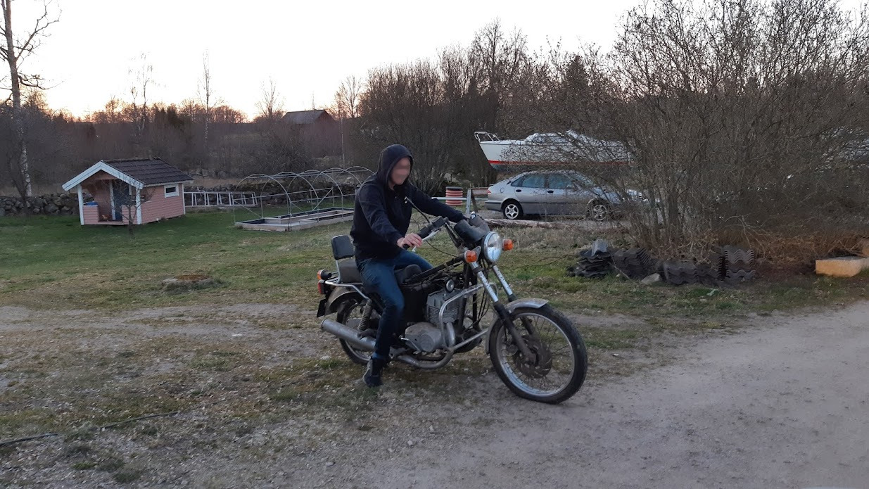
The short story behind it is that it's my dads old bike. It had been collecting dust for many many years. Mainly because the vibrations travelled from the engine straight up into the handlebars quite bad and the final straw was that it got hard (impossible) to start up after one winter. So he ended up never using it with the dream of maybe one day use the motor for a Go Kart or something.
I snatched it up 2019, started stripping it down in a garage me and some acquaintances had together. Unfortunately I didn't live anywhere near the garage so the project was a depressing reminder of me not doing what I wanted until this year when me an my better half bought our first house.
So I started 3 months ago and it's an ongoing project as of writing this.
The build
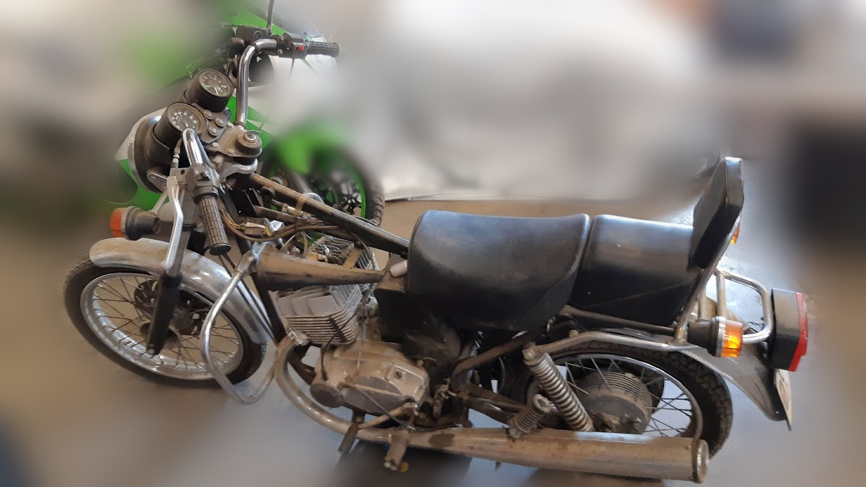
So I began stripping away everything essentially, because I knew I had to figure out a mounting bracket for the motor as well as other stuff. So once in the garage, it looked like this:
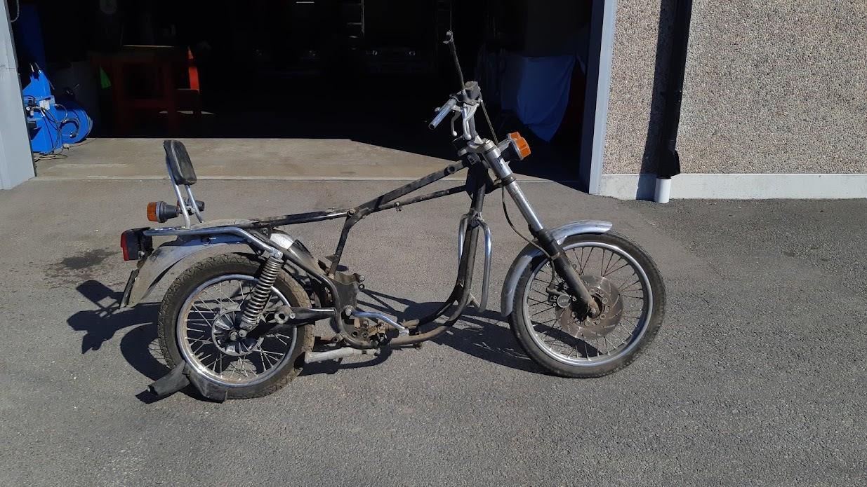
But quickly turned into this:
As most of you who've done something like this, probably knows that this is the fun and easy part.
Just going nuts and taking everything off goes pretty quickly.
The mistake I made here, was letting the project sit unsupervised in the garage among acquaintances. Because when I returned a couple of months (a year?) later most of the stuff I took off was either sold to the scrap yard across the street or thrown away because "it looked liked junk". So what's in this picture is what I actually started out working with.
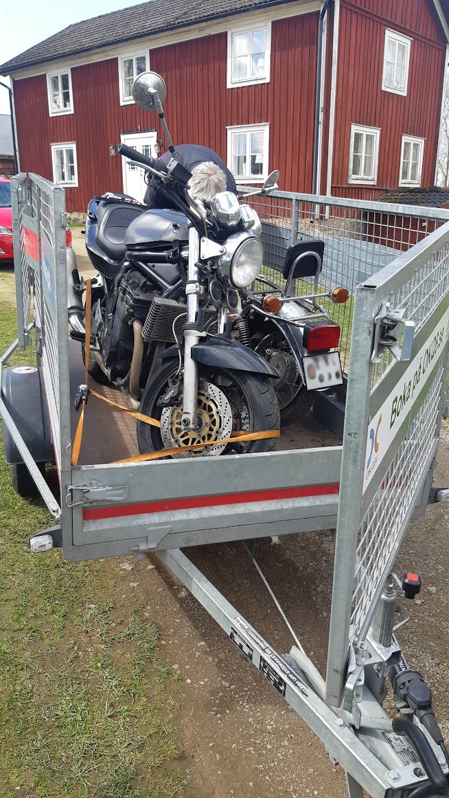
Fastforward from April 2019 to May 2021, when we transported the bike back to where I picked it up in preparation for the final move to our new house (along with the daily driver, a bandit from the same era). And I gotta say, looking back at what state the bike was in at the time.. ouff, not proud to have left it worse than it was when I picked it up.
In June, 2021 I was finally unpacked and got the bike down into the basement of the house (yea, no proper garage here..).
I set up some basic tools and brought in a second mechanic on the project.. Mainly to supervise the whole thing. Great at catching bugs, not much else.
And I began fabricating some motor mounts, figured I'd start there.
(Again, I'm no fabricator so I'm pretty much learning by failing here.. Used some old scrap sheet metal because cardboard box became to inaccurate).
Bolted on more or less dead center.. *cough*
Alignment issues when drilling aside, turned out pretty good for a mockup.
And size wise I think the motor was a pretty good fit.
Now I needed something more permanent and stronger.. Because 1.2mm (yes, I'm a metric cowboy and that would equate to 0,0472441 inches I believe) sheet metal wouldn't really hold up any kind of testing even.
So I used CAD to sketch something up, sent that to my brother who built his own CNC cutter, bent things into shape, center punched better than I ever could and sent the result back to me. I drilled everything out and motor mount was done:
At this point I realized that one of the things I was missing (and I would come to realize this a couple of times) was the rear sprocket. It wasn't an ordinary motorcycle sprocket so finding a replacement would be hard, or so I thought until I found a replacement (https://www.jawashop.com/rear-chain-wheel-52t-complete-jawa-634-640_z2491/) for 80$. Found some other stuff and ordered.
While waiting I started sketching up the battery box out of the same old scrap sheet metal I had laying around.
Mocked it..
Bent it in a vice... (lord knows I wish I had a proper brake)
Assembled it.. And realized it looks like garbage. Not at all as sci-fi as I thought it would be.
So I left that part of the project for a while and started on the drive train.
I custom ordered a sprocket because I don't have any tools to create one.
When that arrived, happily so did the rear sprocket. Fit perfectly.
Then I started working on the seat, because that was thrown away as well apparently.
Used some modeling clay and cardboard box to cover the empty voids. And I would later come back with epoxy and fiberglass to mold a seat.
I was still annoyed with the battery box, so I decided to work on the battery modules inside.
Seeing as I'm using Li-Po I wanted something that was fire retardant and would protect them appropriately from rocks, bumps etc.
And full of myself, thinking I've learned how to bend stuff on a home made brake.. I started fabricating battery boxes for each cell.
Anyone with 20/20 vision can tell that this ain't the work of a professional metal worker.
But I was pleased with getting the dimensions mostly right and getting some hang of it. I was having fun!
But I wasn't satisfied one bit.. So I 3D-printed some enclosures instead..
And put some fans on them. Very silent Noctua fans that run straight of the 12V system with PWM support.
And that was all I managed up until Aug 2021, after which vacation ended and a bathroom renovation had to come in the way.. Which was in the neighbouring room so everything in there occupied the workshop for the better part of 9 months...
I also needed more space in the workshop because I didn't really have anywhere to do any work, it was mostly two wooden stand with a flat bench top on top where I did all the work.
So a side project started of building a proper workbench.
CAD to the rescue, ordered the wood, and in June 2022 my vacation started again and the build was complete:
(of the work bench that is.. Still nowhere on the bike.. But now I had no more excuses)
Disappointed with the previous battery related things, and with the courage after successfully building a work bench.
I re-thought the whole battery module thing, and instead of bending sheet metal to little success I used L-profiles of aluminium, sheet metal and fasteners for more correct angles and stiffness.
Mounted the motor controller on the back side of the battery box
Happy with the result overall, I started the wiring job of everything.
I used 2AWG cabling since I didn't want to risk burning wires when pushing a lot of amps (trying to do my math since thickness and length increases resistance..)
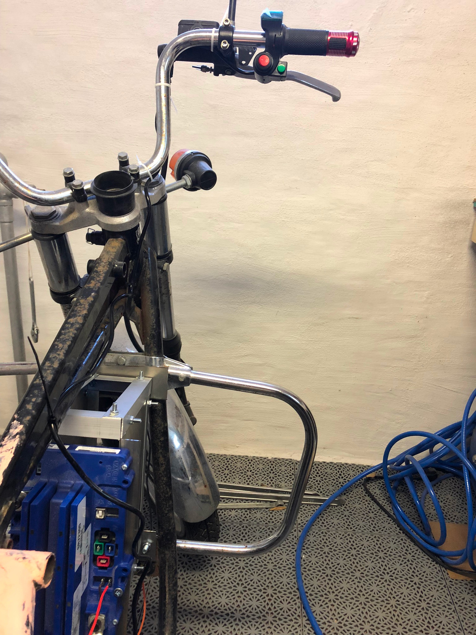
Inductance handlebars from ebay, banggood or aliexpress.
Used an old power supply from a LED/fish tank project that could deliver 12V. Just to test out that the motor controller and handlebars were connected the right way around without risking anything.
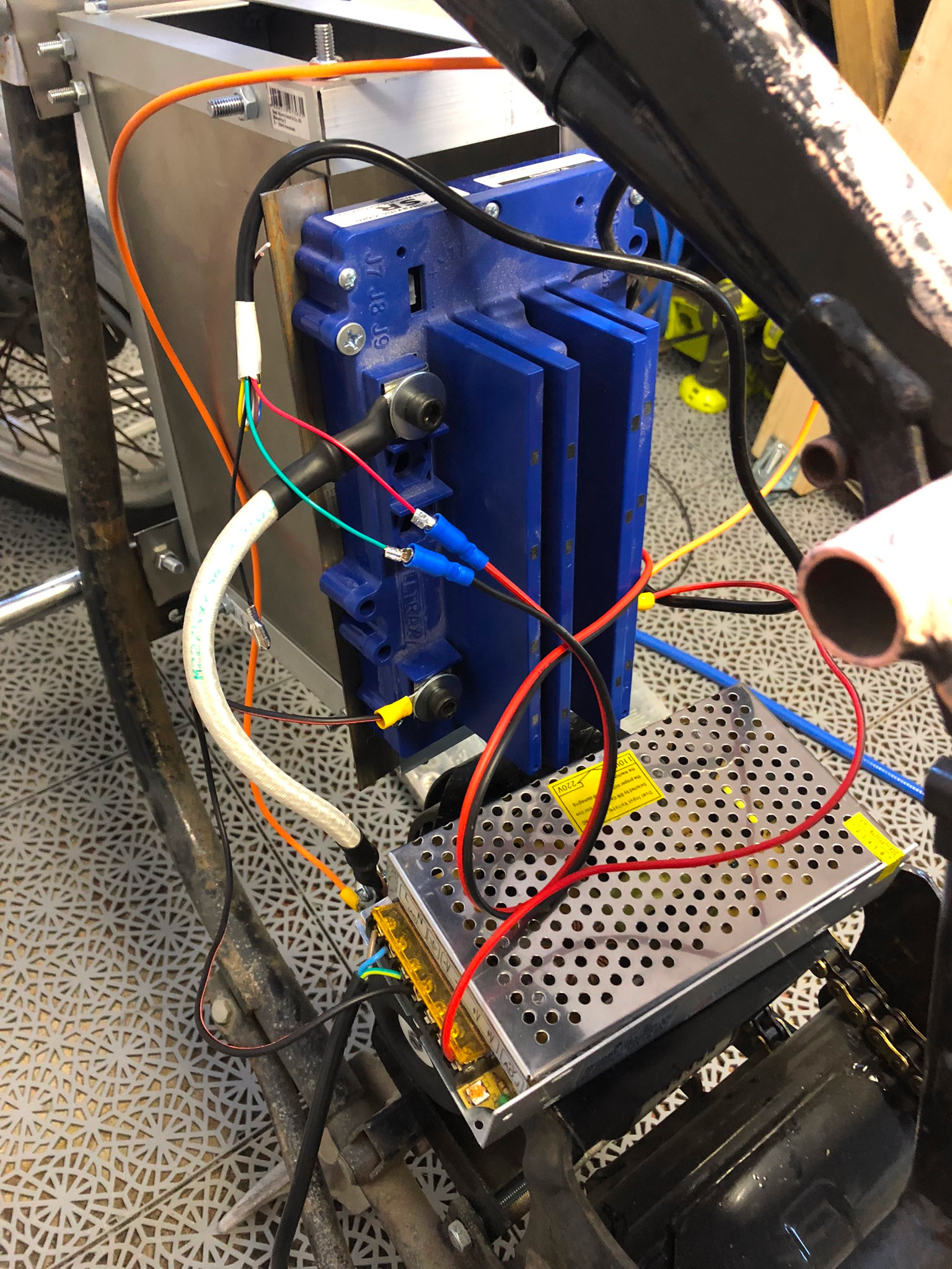
And sure enough, it works:
https://youtube.com/8Xbtfg3tvJw
Once I knew it was working I added some safety features before hooking up the full 82V to everything.
A solenoid/contactor from Altran Magnetics, ALEV200 200A. Some fuses and capacitors to soft start the thing when plugging in everything. I'm not perfectly happy with the placement of the contactor, as the bend radius on the power cables are a bit.. iffy.
But they'll do for now.
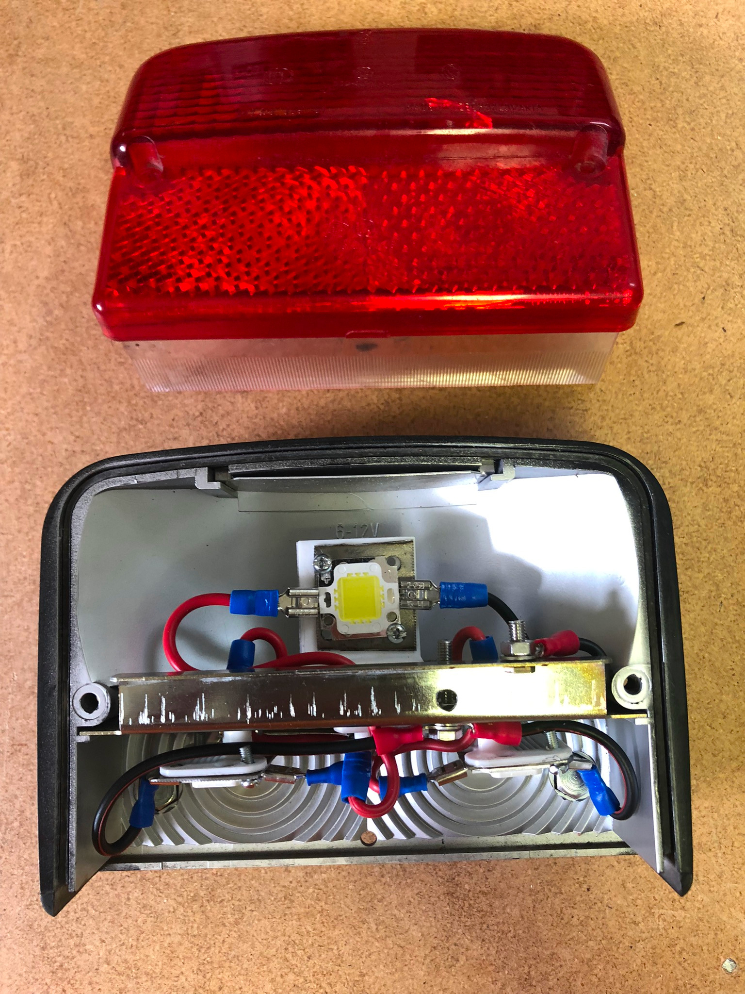
Happy with that result, I started fabricating the light bulb replacements for the original light houses.
I settled for 10W LED's that I could control with PWM. After attempting metal work once more to no success I default back to 3D printing. It's PLA right now but I'll use some sort of nylon-reinforced material later.
Final result turned out pretty good. I could have been a bit generous on my tolerances as it sits there pretty damn snug.
Was a PITA to thread the 15 AWG cabling through the slots i made in the bulb stem.
It's at this point I realized I need a 82V to 12V converter, so I ordered that one.
And while doing so I realized I probably want to test the "battery" power without actually using batteries as they can go poof if anything is connected incorrectly causing a short. So... I got my hands on a bench power supply from Delta Elektronika which is by far my best purchase so far in this project.
(Second hand but damn the quality on these things..)
So I bodged together a control cluster (because you guessed it, that was thrown out too).
Cleaned up some wiring..
Created a mock control circuit
Programmed it under my trusty old workshop supervision
(I do clean quite zealously since she really loves hanging out with me down there)
Snapped the control cluster in half because 2mm acrylic isn't very strong.
So bodged together one from and old kitchen sink.
Happy to say that the logic works.
[youtube]https://youtu.be/w1NSw7879Tw[/youtube]
I continued to hook everything else up electronics wise.
Back light house was a bit tricker because they shared a common ground and the MOSFET drivers control ground not positive voltage.
So the positive terminal of the break light is separated from the otherwise common +12V that the license plate light share. And then i PWM ground via the common ground just to not over heat them all. Positive voltage for the break light goes through the break pedal relay that came with the bike, that way it can light up independently and mechanically while still getting the PWM benefits.
Refitted the rear tire as it was blown, will do the same with the front soon as the rubber is very old but still intact for a testrun.
And this is one of those moments when everything looks like it's coming together pretty well.
Added the 12V converter, and all the mosfet drivers on a little acrylic test piece.
And this is when the wiring mess hit me..
Luckily, the headlight arrived and got me distracted like a chipmunk for about 12 seconds.
Until I found out that I know nothing about Jeep Wranglers and car headlight fixtures.. Apparently they use a trim ring to connect hings so there was no mounting holes on the headlight..
Fear not I thought, I'll make one.. two.. well three "trim rings" until I got one that worked.
And it fit and looked pretty decent.
(Keeping with the theme of not being able to align a single thing, it's crooked but centered on the shocks at least)
3D printed a new control cluster to get everything to fit more snugly.
Looked like garbage and was way to thin to support anything so did a second one..
Turned out a lot better but had to re-do it a third time to get the screw holes sturdy enough.
Disappointed with my CAD skills in terms of mechanical strength I embarked on using Epoxy and fiberglass for the first time.
I've been putting this off for a long time due to smell, fear and not knowing what to do if I get it everywhere..
But I slapped on a thick coat of gel coat to get the contours right.
Let it rest for a bit, put some fiberglass on top and drenched it in epoxy.
And it turned out pretty good. After cutting it up.
Next up is upholstery, learning and failing there.
I also learned the other day that metric bolts and nuts have different thread sizes. There's fine thread and coarse threads.
Apparently the wheel shaft at the back wheel has a 1.5mm fine thread on a M14 bolt.. Not something that appears to be common as all nuts and bolts have a 2mm thread on them where I live. So I've ordered the most expensive nut I've ever ordered and while waiting for that to arrive, I'll youtube some upholstery stuff.
And that's where the project is as of today.
I'm out of vacation for 2022, but I'm hoping to get the rest done in the spare time before winter comes.
BMS is on it's way, should arrive within 2 weeks.
I know this has been a long post to say the least, but It's been my journey so far.
My goal with this is to learn as much as possible and maybe do more of these projects.
And to share back to the community what I've learned over the year or so.
Feedback is welcome, but keep in mind that I'm probably the greenest rookie on the forum. So be gentle")
First off, it's fun to finally have found a forum dedicated to DIY EV's.
Secondly, go easy on me. First time fabricator, electric vehicle builder (more or less) and overall new to the forum.
And lastly, I'll take you on a bit of a journey because it's been a long and lonely project.
So what am I cooking?
I'm currently in the later stages of completing a old 1995 Jawa rebuild. Going from 343 cubic centimeter, 17kW petrol powered motorcycle to a rated 6kW (Peak 21kW) power with 18.2 Nm of torque which aligns well with the old chain drive alignment.
Technical specs
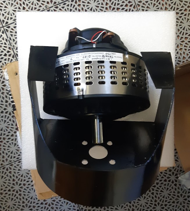
- Motor: Lynch motor, model LEM-170-D127.
- Battery: Li-Po 5S batteries, 4 of those in series so 20S pack (82V). With a rough rated discharge rate of 170A.
- Controller: Alltrax SR72300 (Not ideal, but it comes with the motor more or less)
- Gearing: 2.737 : 1 (Should top out at roughly 120km/h, or 74,5645mph)
- BMS: Daly 250A
- 12V system: A random Amazon buck/step down converter from 82V down to 12V
- Lights and controls: Arduino Nano with Mosfet+Drivers to control everything
- Headlight: Amazon replacement light for a Jeep Wrangler called "Sunydog"
- Blinkers & Brake light: 10W LED COB's on a 3D-printer Bulb mount
Backstory
So the bike started out as this:
The short story behind it is that it's my dads old bike. It had been collecting dust for many many years. Mainly because the vibrations travelled from the engine straight up into the handlebars quite bad and the final straw was that it got hard (impossible) to start up after one winter. So he ended up never using it with the dream of maybe one day use the motor for a Go Kart or something.
I snatched it up 2019, started stripping it down in a garage me and some acquaintances had together. Unfortunately I didn't live anywhere near the garage so the project was a depressing reminder of me not doing what I wanted until this year when me an my better half bought our first house.
So I started 3 months ago and it's an ongoing project as of writing this.
The build
So I began stripping away everything essentially, because I knew I had to figure out a mounting bracket for the motor as well as other stuff. So once in the garage, it looked like this:
But quickly turned into this:
As most of you who've done something like this, probably knows that this is the fun and easy part.
Just going nuts and taking everything off goes pretty quickly.
The mistake I made here, was letting the project sit unsupervised in the garage among acquaintances. Because when I returned a couple of months (a year?) later most of the stuff I took off was either sold to the scrap yard across the street or thrown away because "it looked liked junk". So what's in this picture is what I actually started out working with.
Fastforward from April 2019 to May 2021, when we transported the bike back to where I picked it up in preparation for the final move to our new house (along with the daily driver, a bandit from the same era). And I gotta say, looking back at what state the bike was in at the time.. ouff, not proud to have left it worse than it was when I picked it up.
In June, 2021 I was finally unpacked and got the bike down into the basement of the house (yea, no proper garage here..).
I set up some basic tools and brought in a second mechanic on the project.. Mainly to supervise the whole thing. Great at catching bugs, not much else.
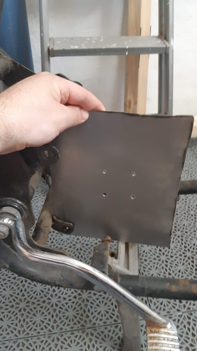
And I began fabricating some motor mounts, figured I'd start there.
(Again, I'm no fabricator so I'm pretty much learning by failing here.. Used some old scrap sheet metal because cardboard box became to inaccurate).
Bolted on more or less dead center.. *cough*
Alignment issues when drilling aside, turned out pretty good for a mockup.
And size wise I think the motor was a pretty good fit.
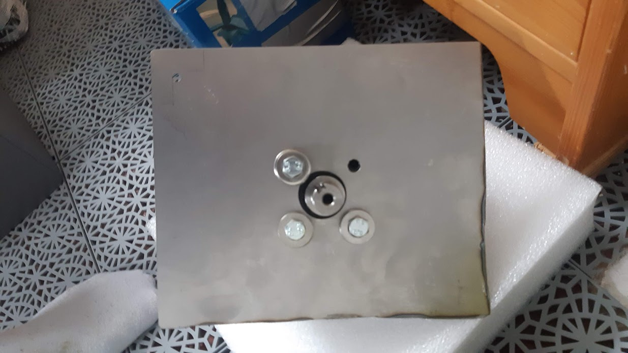
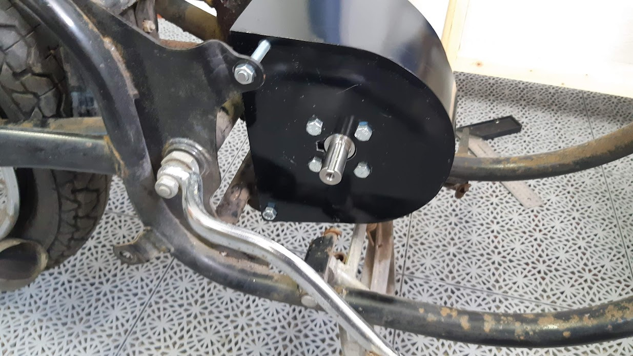
Now I needed something more permanent and stronger.. Because 1.2mm (yes, I'm a metric cowboy and that would equate to 0,0472441 inches I believe) sheet metal wouldn't really hold up any kind of testing even.
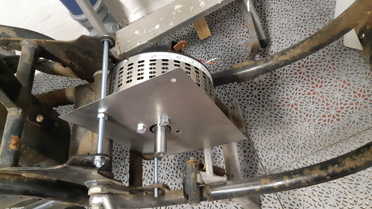
So I used CAD to sketch something up, sent that to my brother who built his own CNC cutter, bent things into shape, center punched better than I ever could and sent the result back to me. I drilled everything out and motor mount was done:
At this point I realized that one of the things I was missing (and I would come to realize this a couple of times) was the rear sprocket. It wasn't an ordinary motorcycle sprocket so finding a replacement would be hard, or so I thought until I found a replacement (https://www.jawashop.com/rear-chain-wheel-52t-complete-jawa-634-640_z2491/) for 80$. Found some other stuff and ordered.
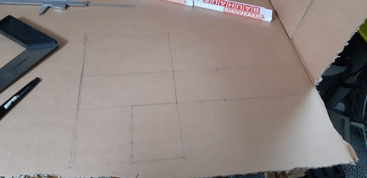
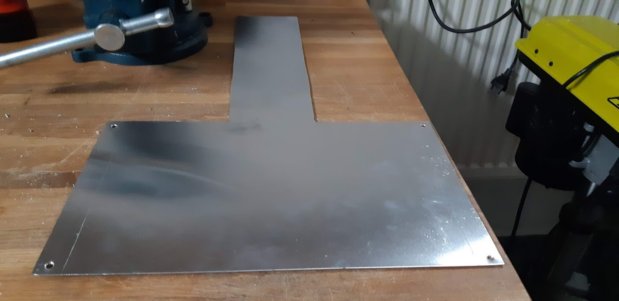
While waiting I started sketching up the battery box out of the same old scrap sheet metal I had laying around.
Mocked it..
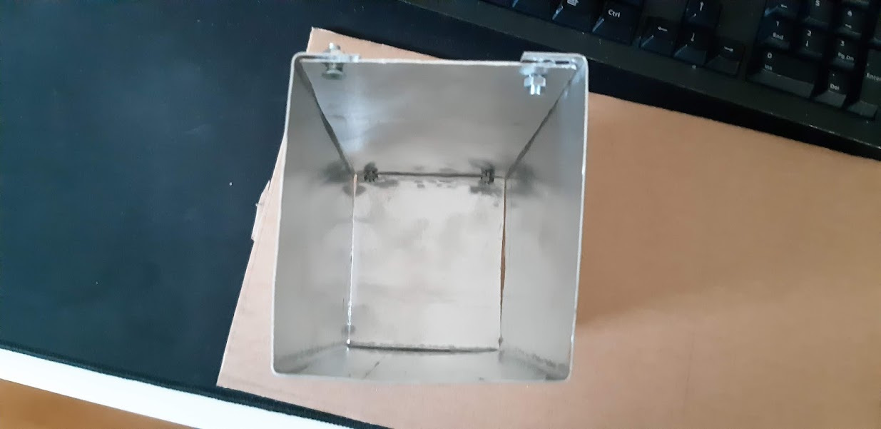
Bent it in a vice... (lord knows I wish I had a proper brake)
Assembled it.. And realized it looks like garbage. Not at all as sci-fi as I thought it would be.
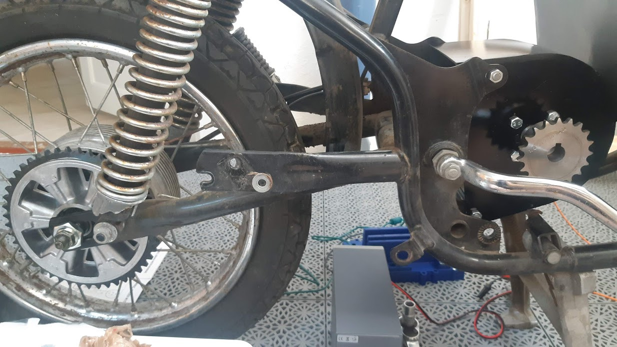
So I left that part of the project for a while and started on the drive train.
I custom ordered a sprocket because I don't have any tools to create one.
When that arrived, happily so did the rear sprocket. Fit perfectly.
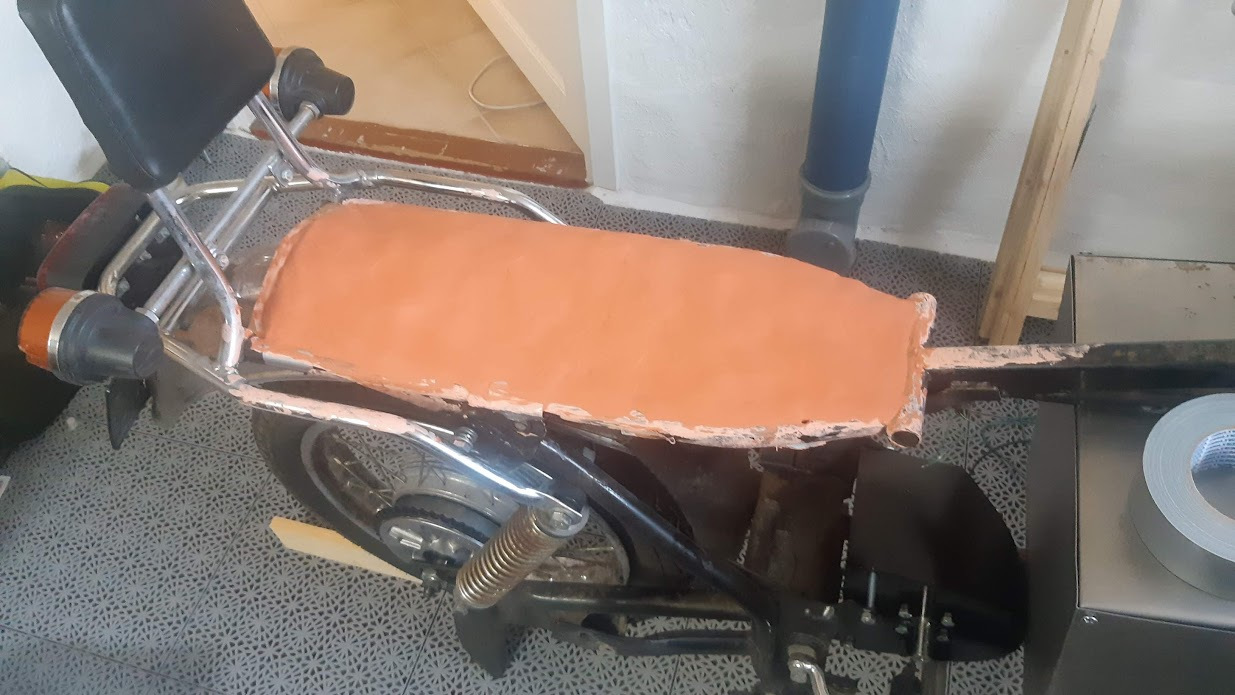
Then I started working on the seat, because that was thrown away as well apparently.
Used some modeling clay and cardboard box to cover the empty voids. And I would later come back with epoxy and fiberglass to mold a seat.
I was still annoyed with the battery box, so I decided to work on the battery modules inside.
Seeing as I'm using Li-Po I wanted something that was fire retardant and would protect them appropriately from rocks, bumps etc.
And full of myself, thinking I've learned how to bend stuff on a home made brake.. I started fabricating battery boxes for each cell.
Anyone with 20/20 vision can tell that this ain't the work of a professional metal worker.
But I was pleased with getting the dimensions mostly right and getting some hang of it. I was having fun!
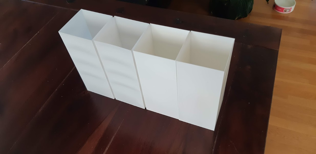
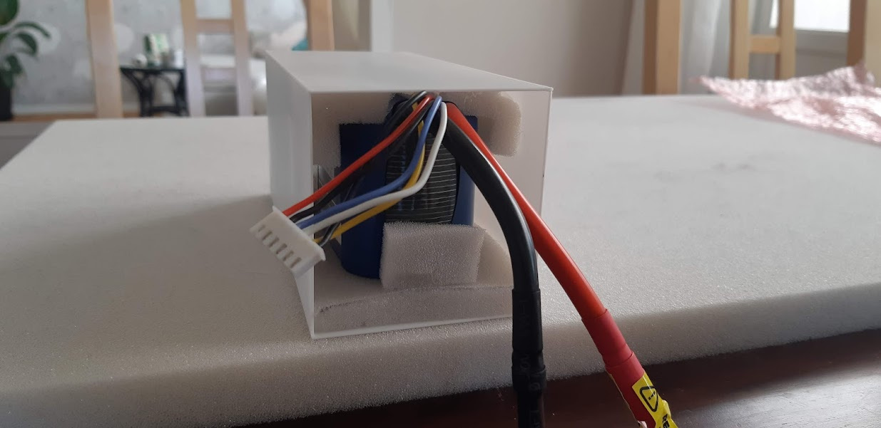
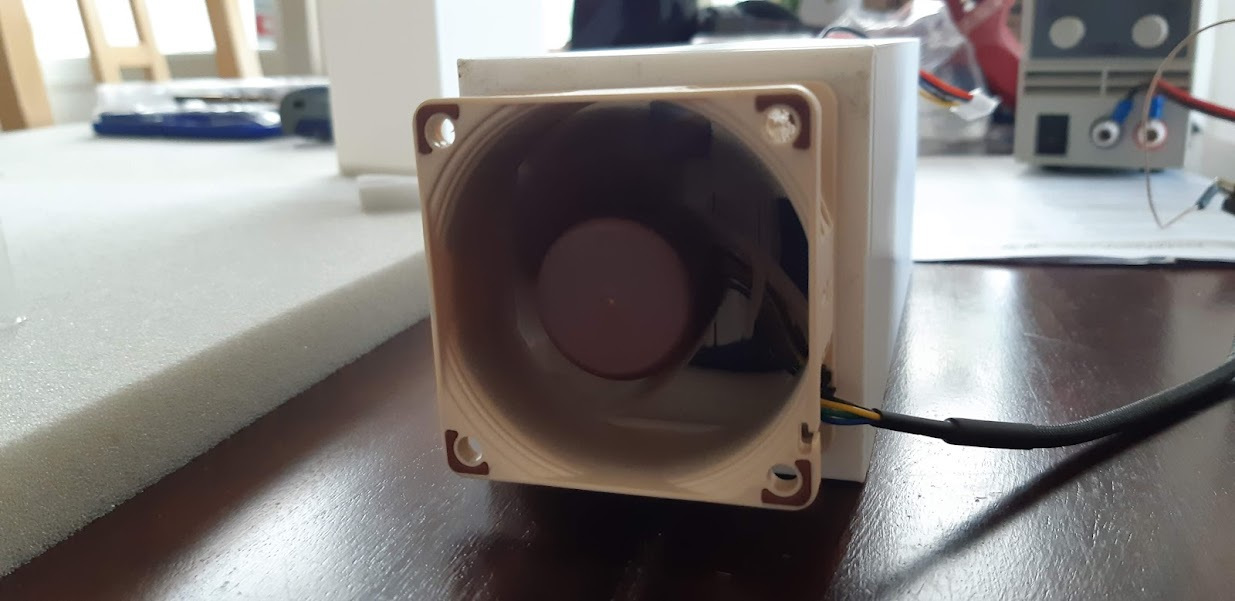
But I wasn't satisfied one bit.. So I 3D-printed some enclosures instead..
And put some fans on them. Very silent Noctua fans that run straight of the 12V system with PWM support.
And that was all I managed up until Aug 2021, after which vacation ended and a bathroom renovation had to come in the way.. Which was in the neighbouring room so everything in there occupied the workshop for the better part of 9 months...
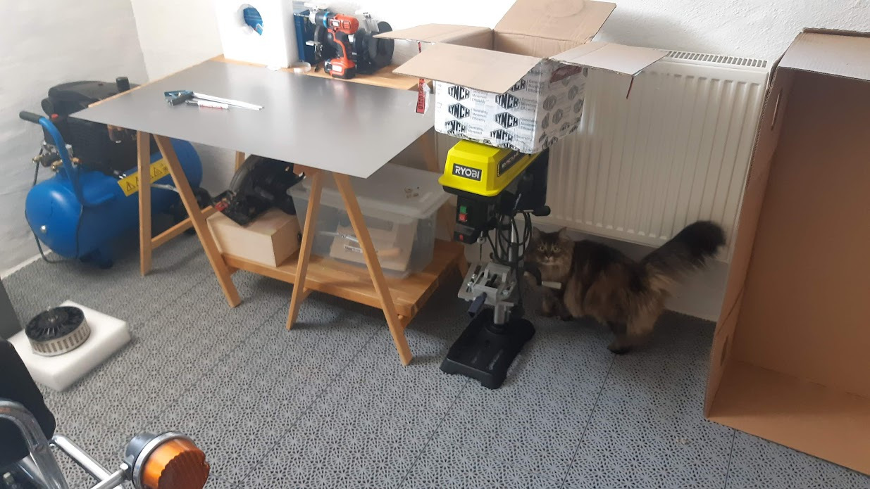
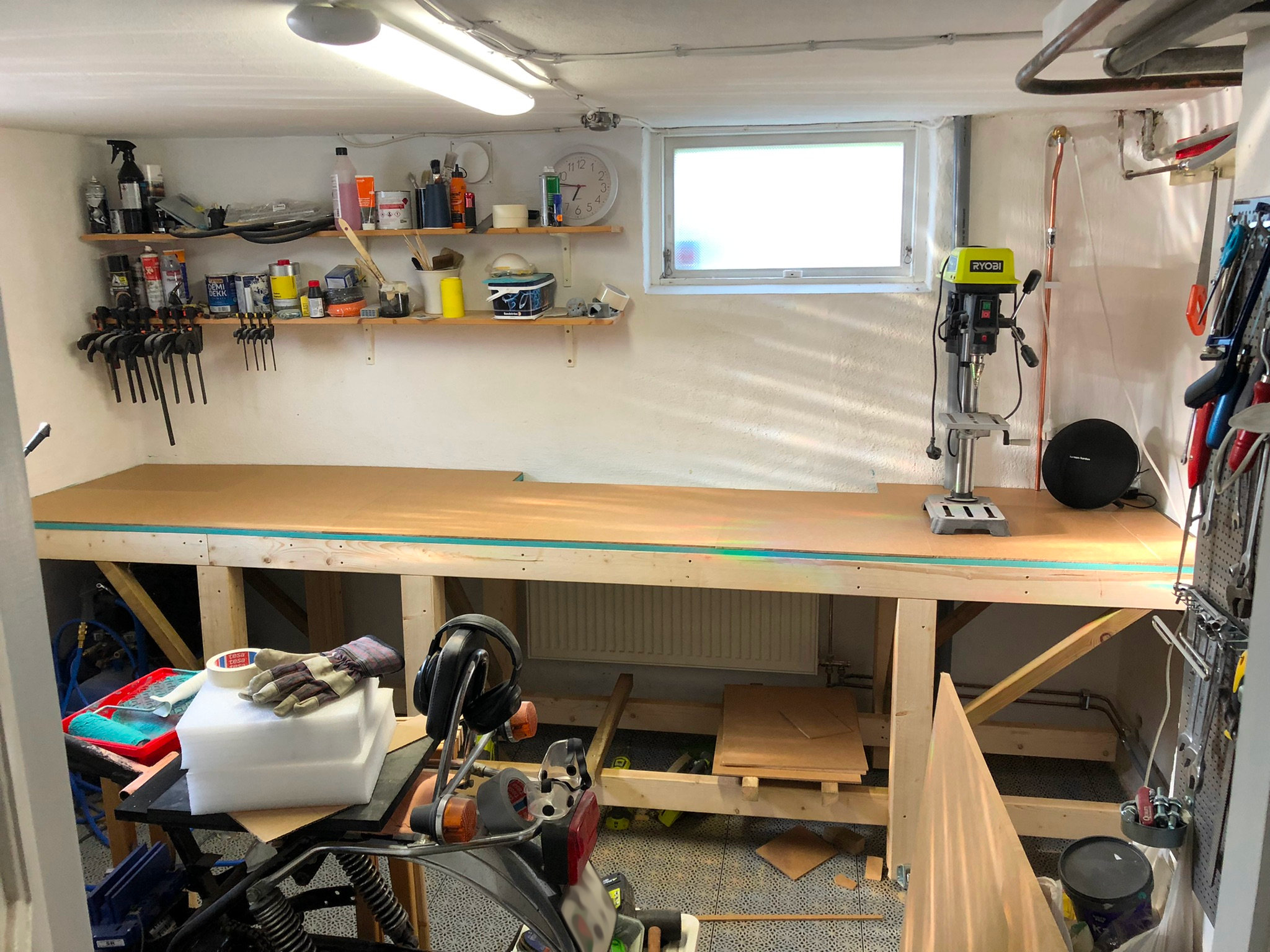
I also needed more space in the workshop because I didn't really have anywhere to do any work, it was mostly two wooden stand with a flat bench top on top where I did all the work.
So a side project started of building a proper workbench.
CAD to the rescue, ordered the wood, and in June 2022 my vacation started again and the build was complete:
(of the work bench that is.. Still nowhere on the bike.. But now I had no more excuses)
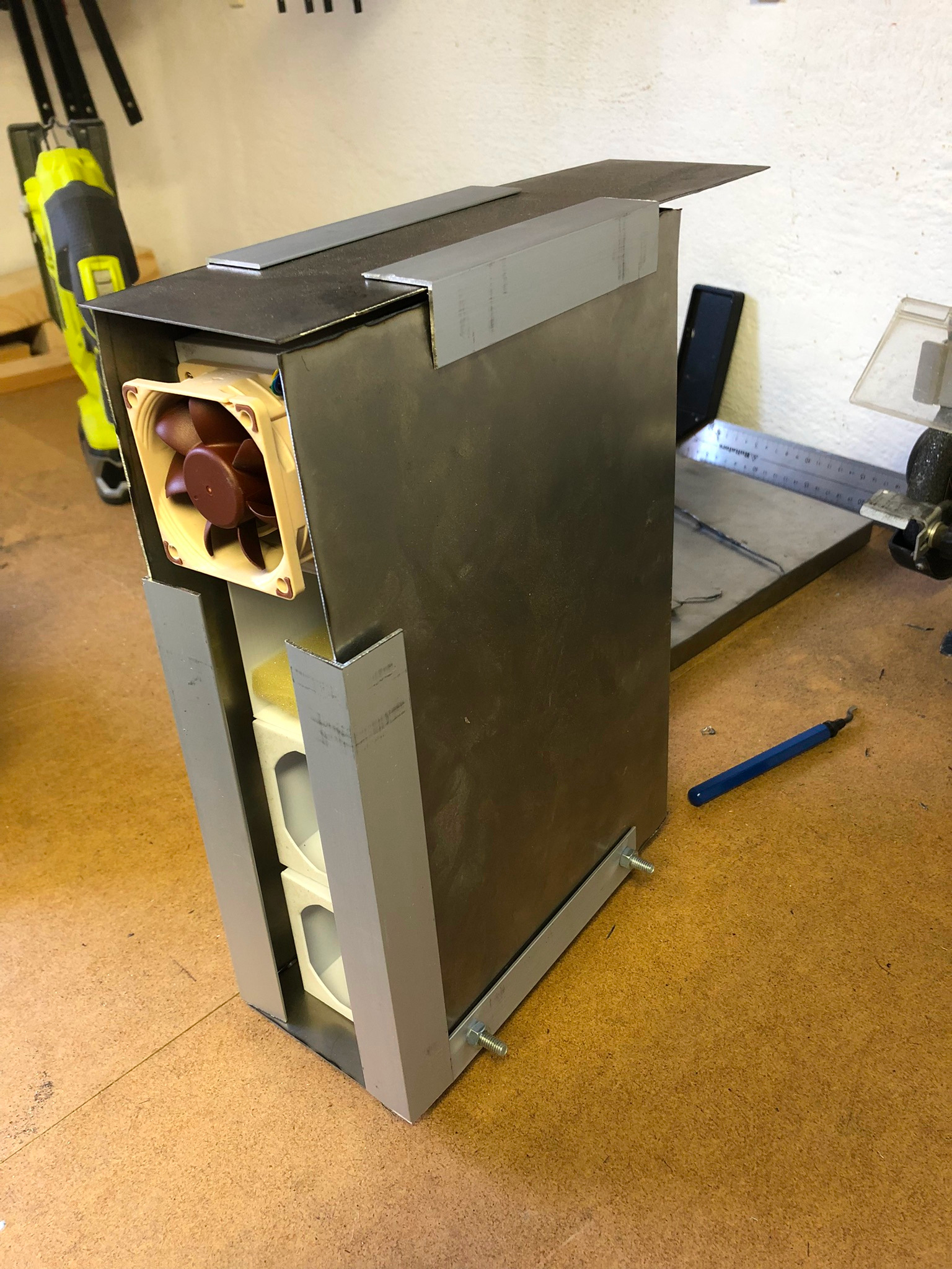
Disappointed with the previous battery related things, and with the courage after successfully building a work bench.
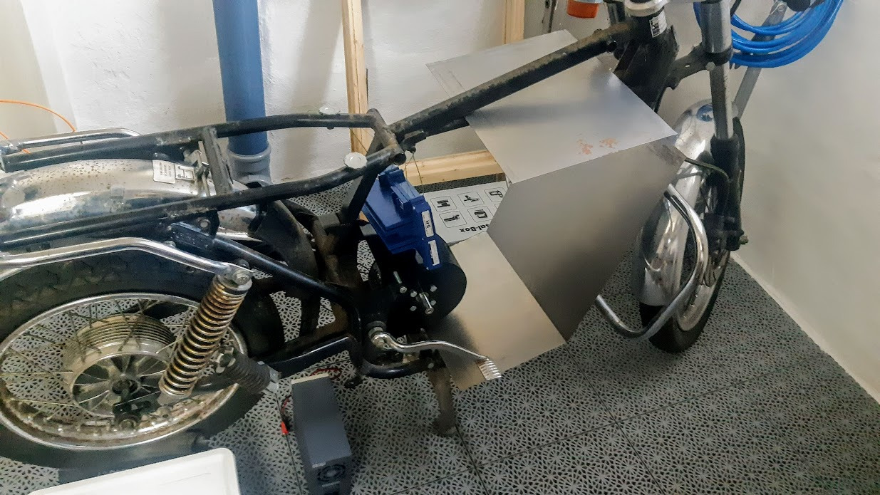
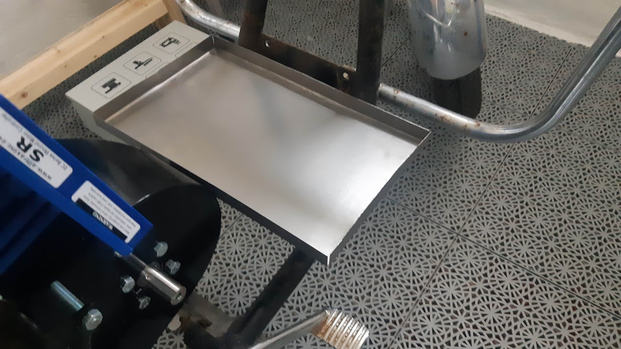
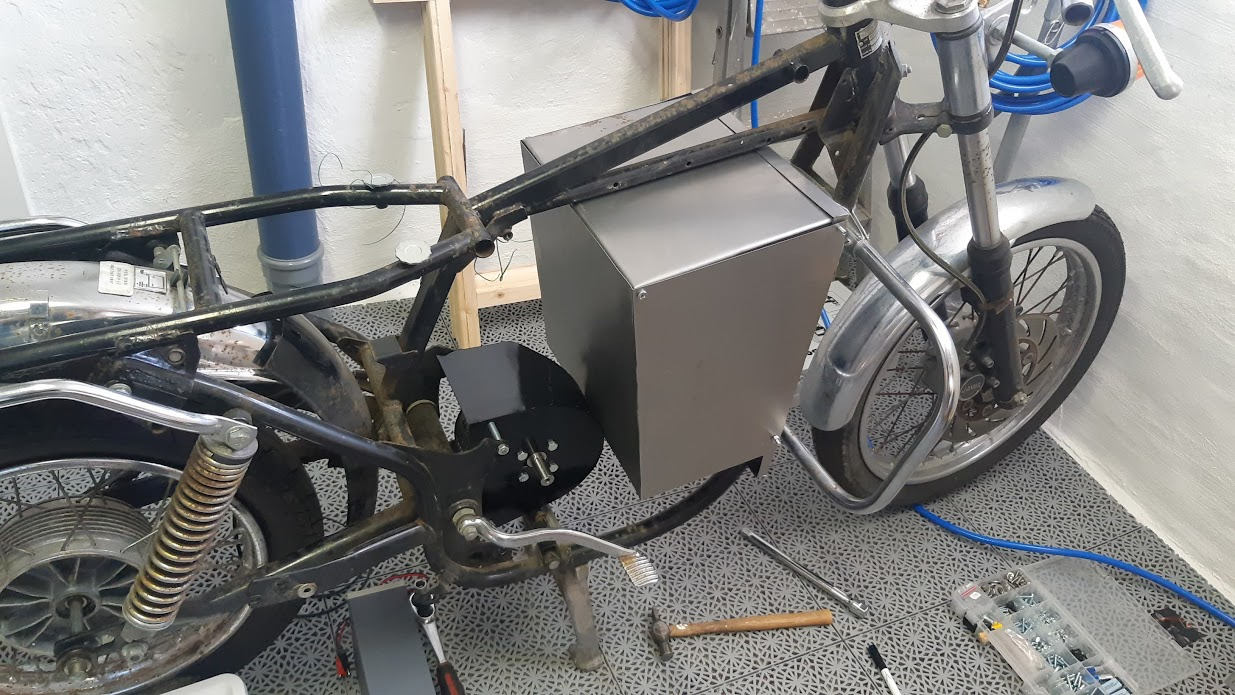
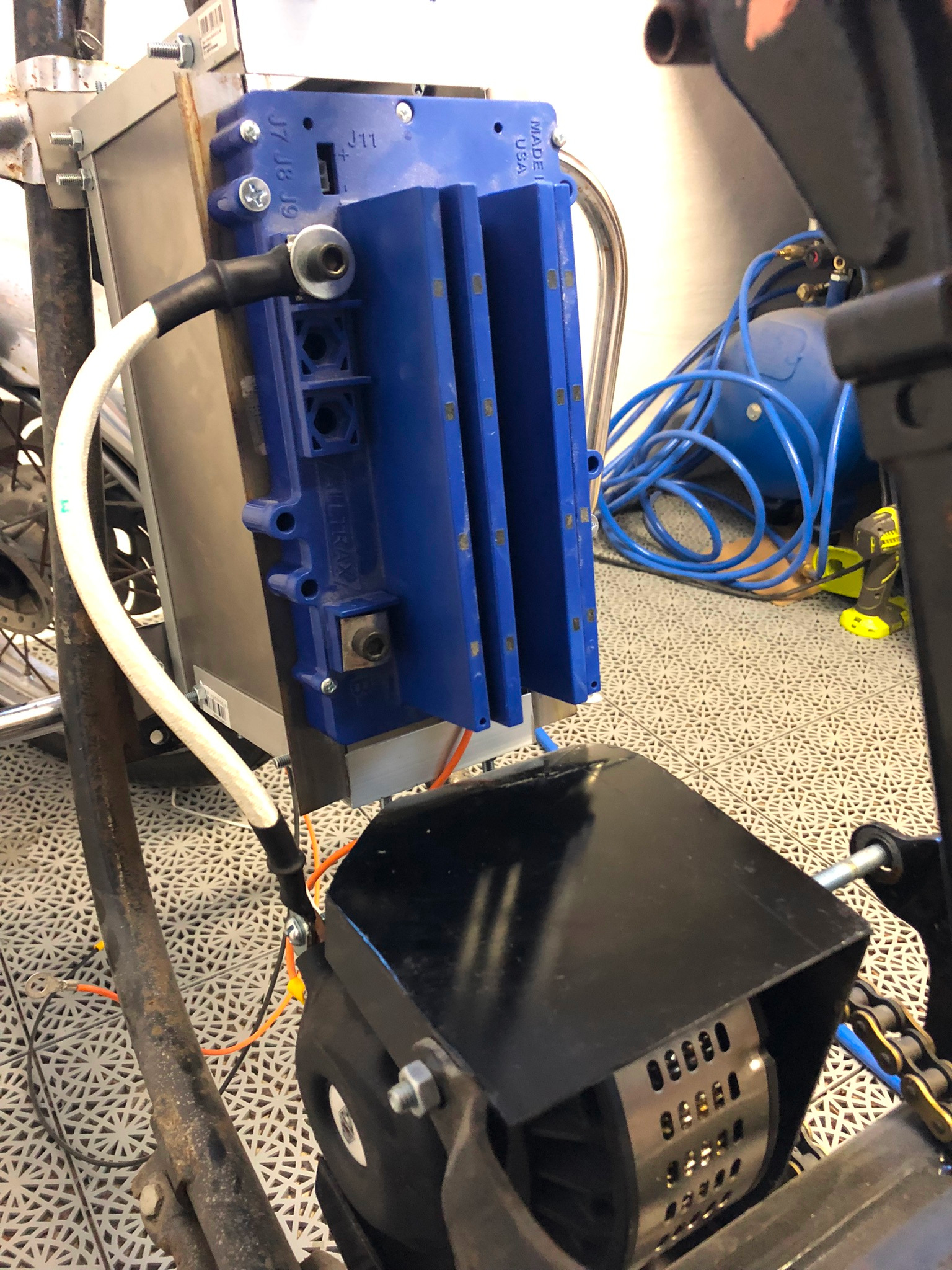
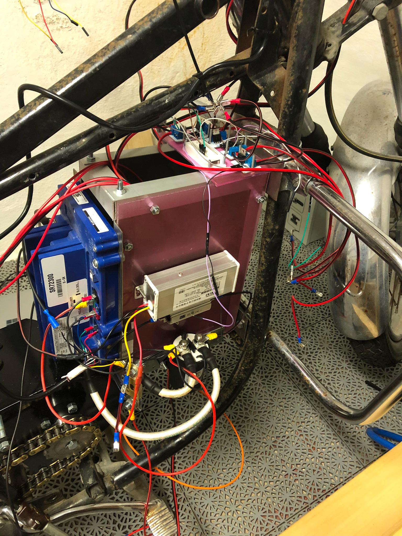
I re-thought the whole battery module thing, and instead of bending sheet metal to little success I used L-profiles of aluminium, sheet metal and fasteners for more correct angles and stiffness.
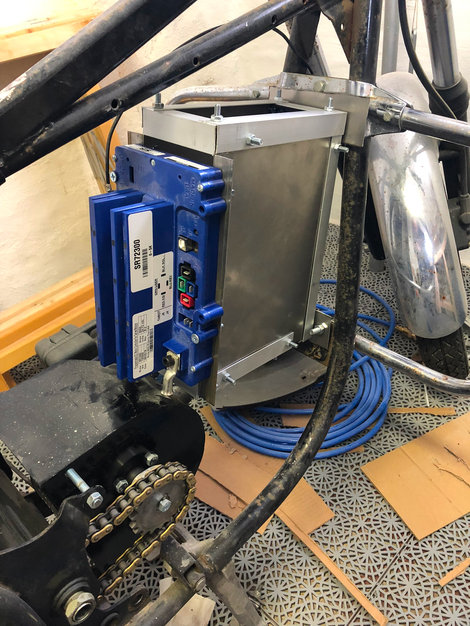
Mounted the motor controller on the back side of the battery box
Happy with the result overall, I started the wiring job of everything.
I used 2AWG cabling since I didn't want to risk burning wires when pushing a lot of amps (trying to do my math since thickness and length increases resistance..)
Inductance handlebars from ebay, banggood or aliexpress.
Used an old power supply from a LED/fish tank project that could deliver 12V. Just to test out that the motor controller and handlebars were connected the right way around without risking anything.
And sure enough, it works:
https://youtube.com/8Xbtfg3tvJw
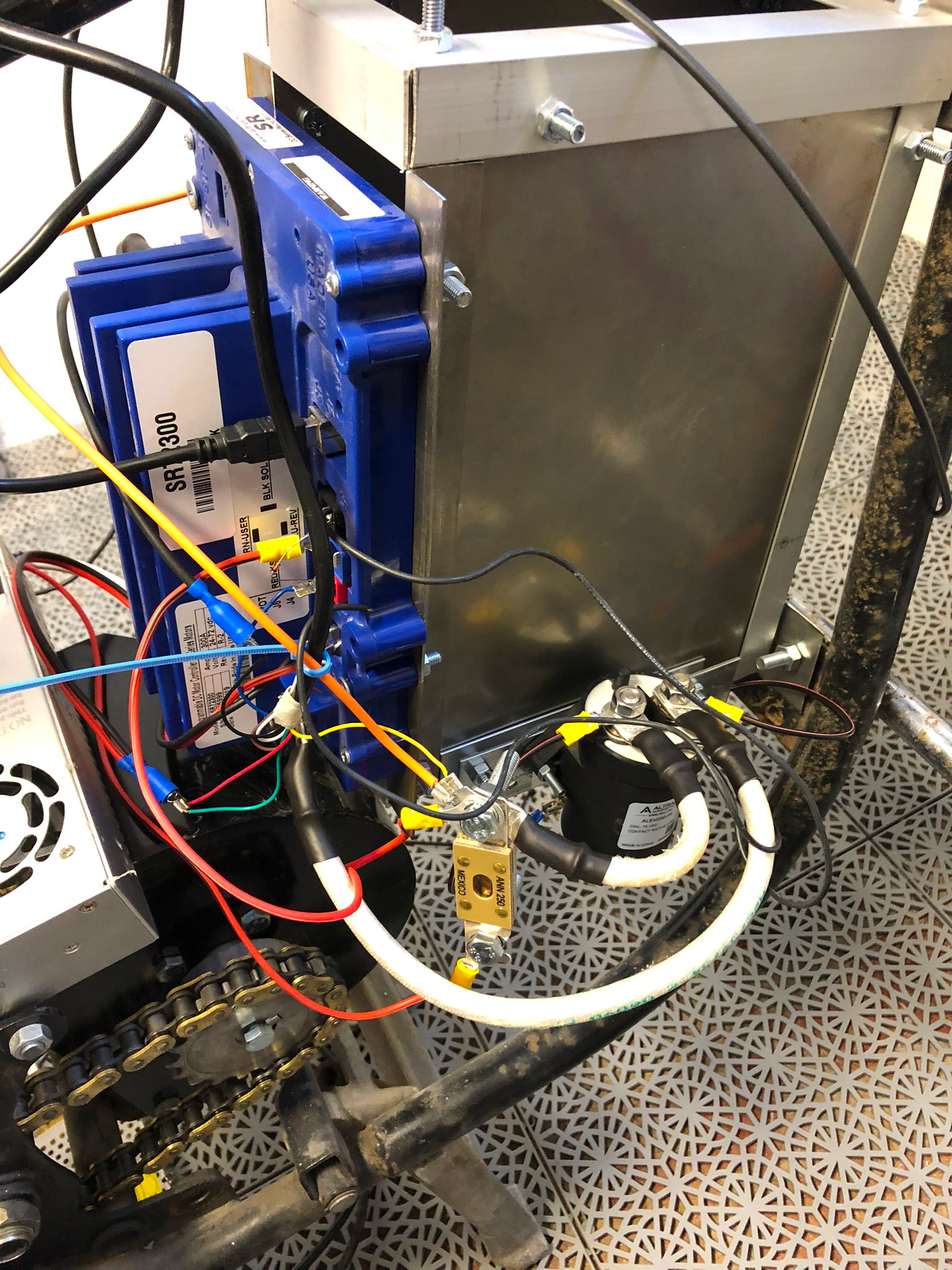
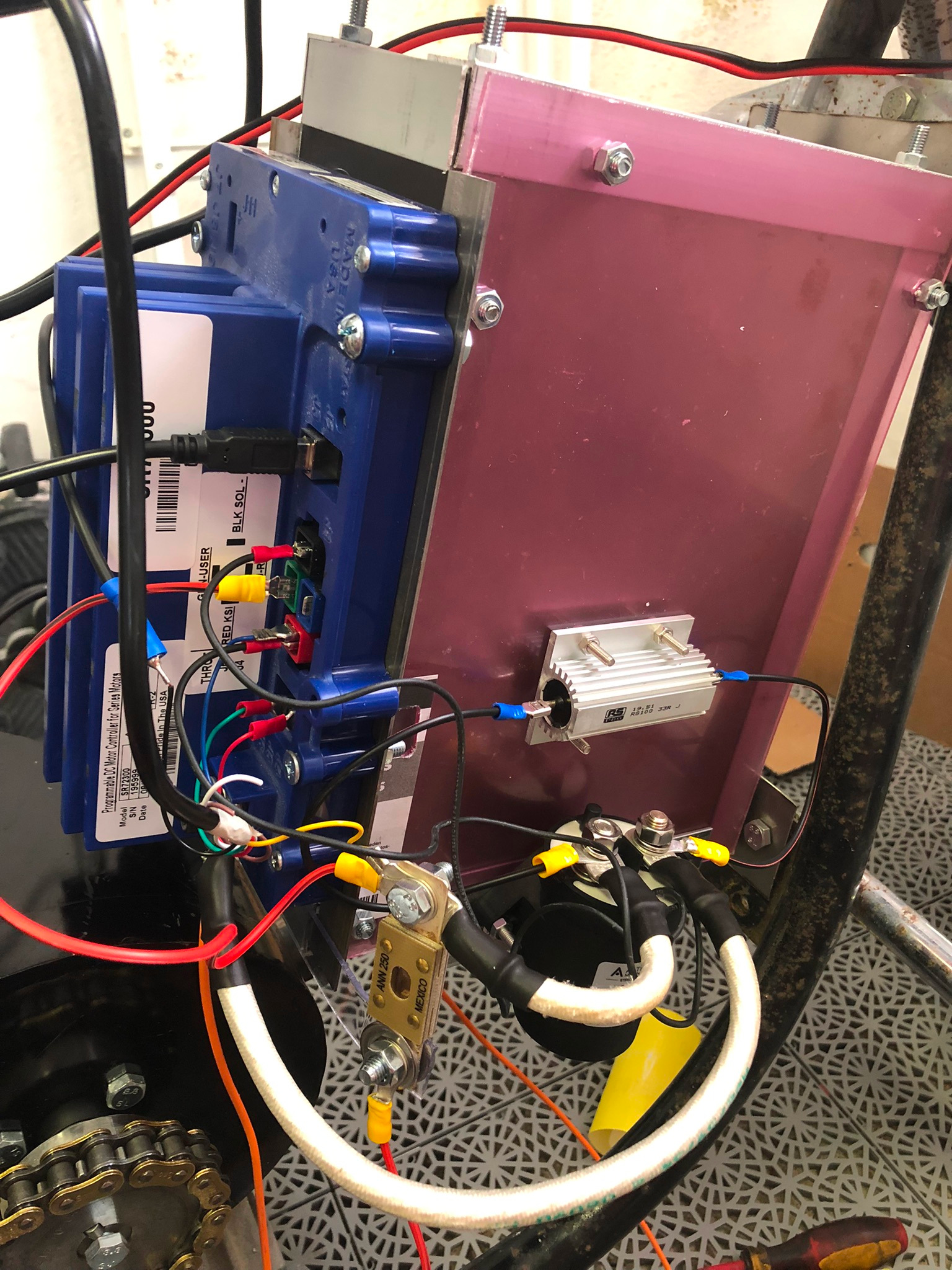
Once I knew it was working I added some safety features before hooking up the full 82V to everything.
A solenoid/contactor from Altran Magnetics, ALEV200 200A. Some fuses and capacitors to soft start the thing when plugging in everything. I'm not perfectly happy with the placement of the contactor, as the bend radius on the power cables are a bit.. iffy.
But they'll do for now.
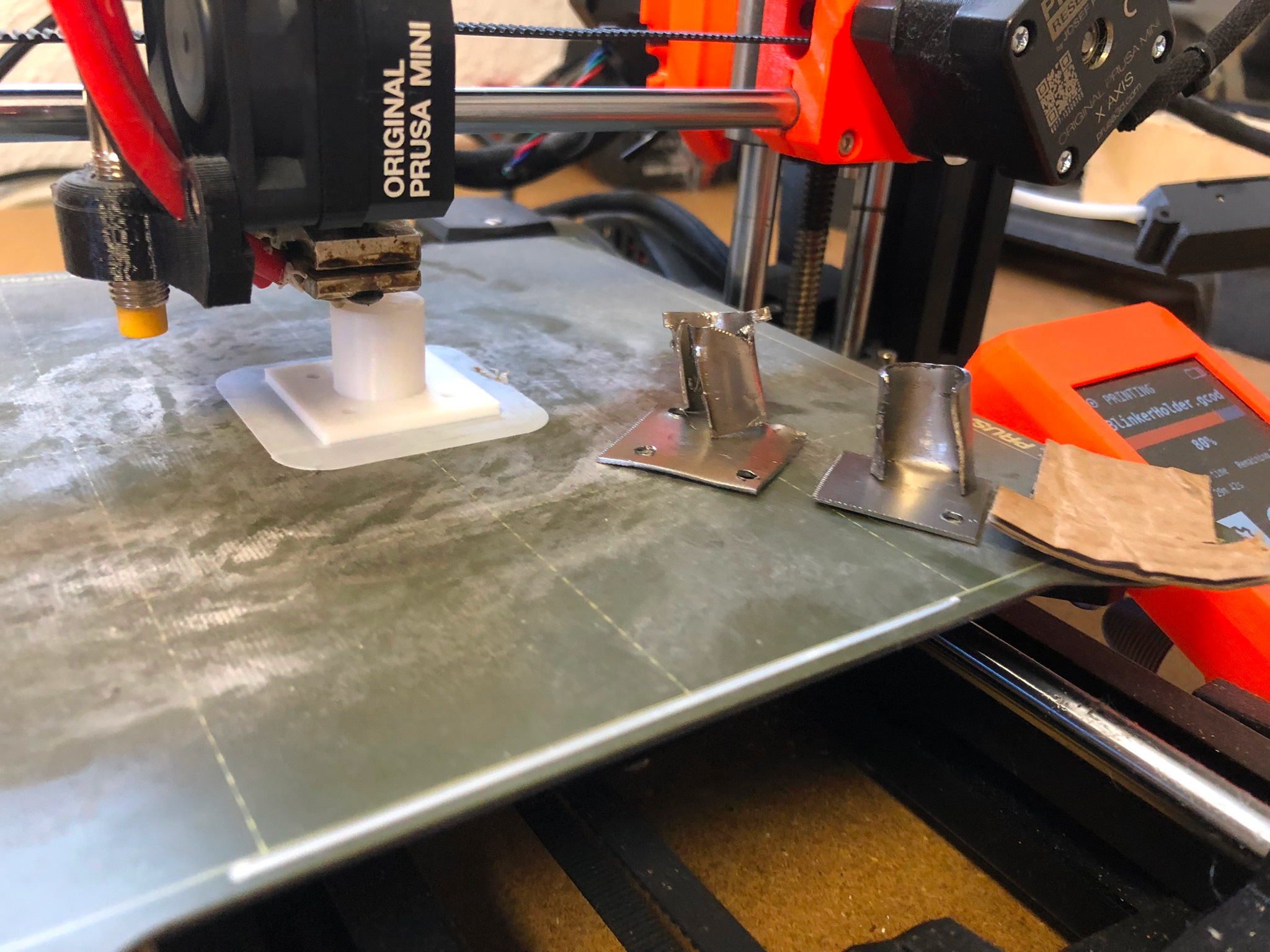
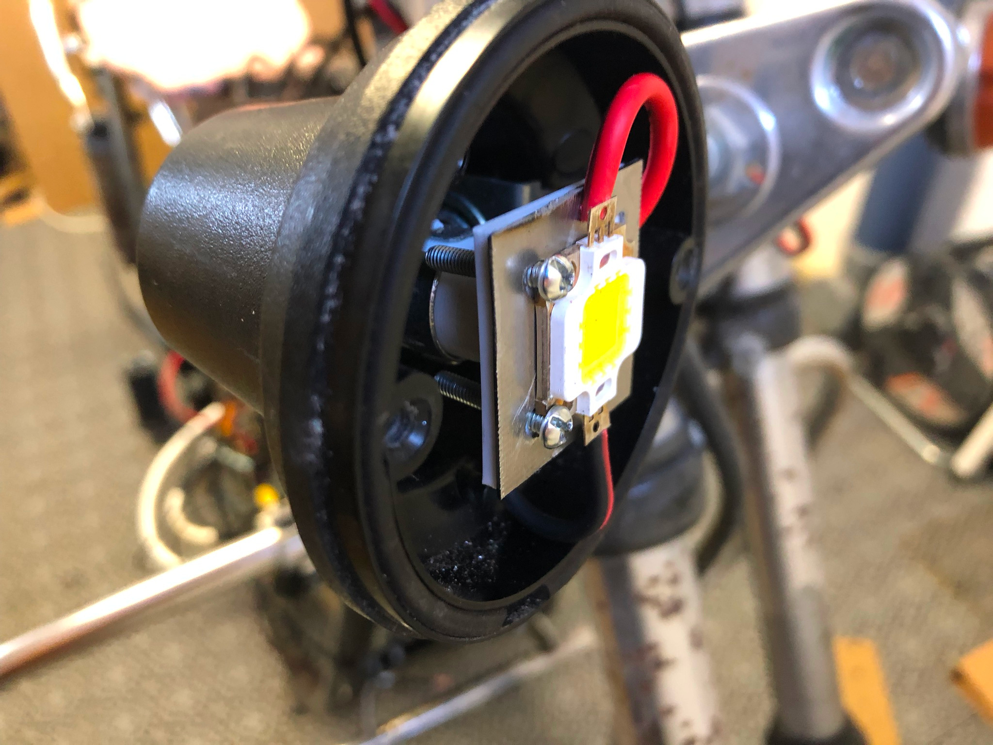
Happy with that result, I started fabricating the light bulb replacements for the original light houses.
I settled for 10W LED's that I could control with PWM. After attempting metal work once more to no success I default back to 3D printing. It's PLA right now but I'll use some sort of nylon-reinforced material later.
Final result turned out pretty good. I could have been a bit generous on my tolerances as it sits there pretty damn snug.
Was a PITA to thread the 15 AWG cabling through the slots i made in the bulb stem.
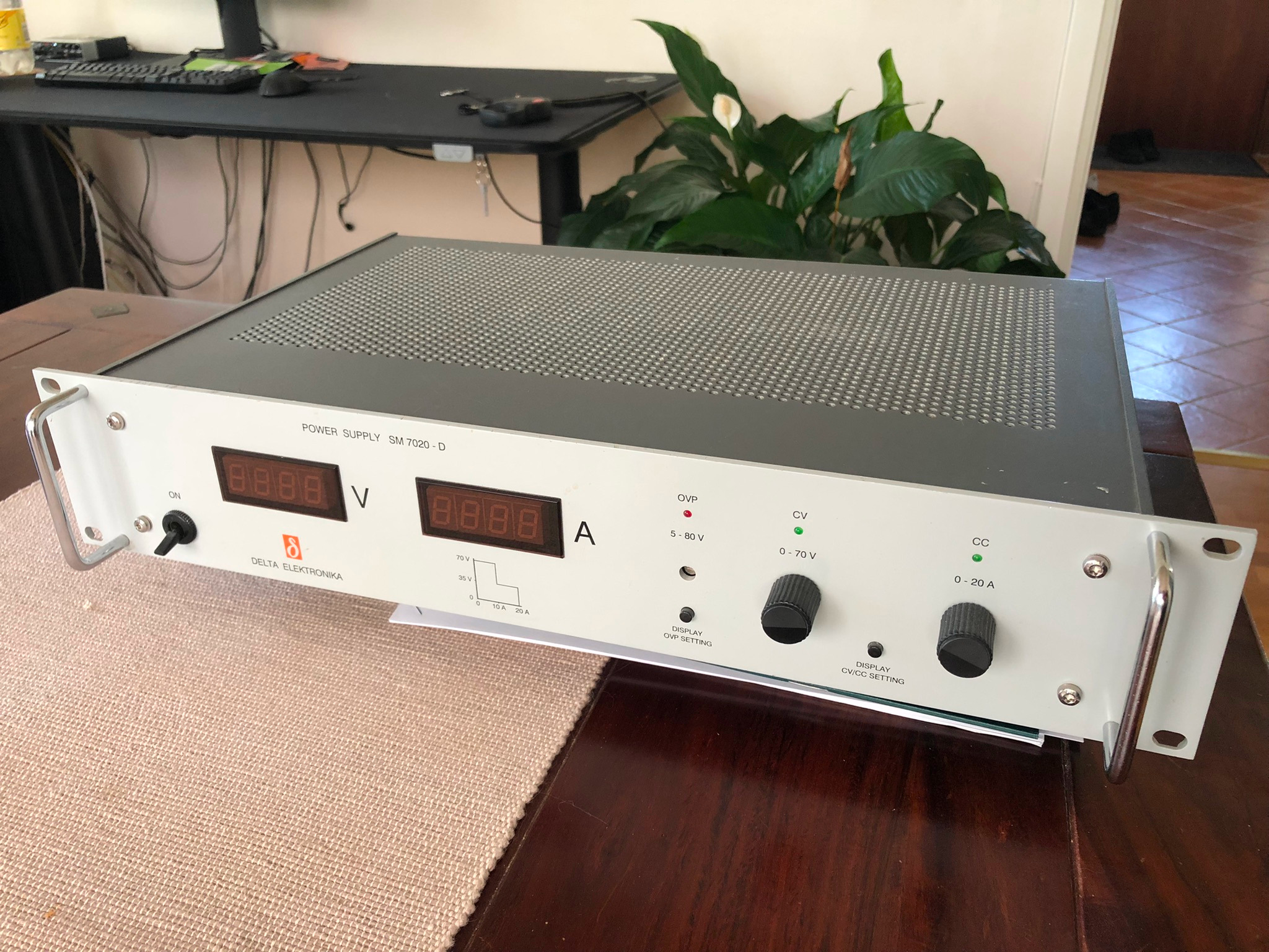
It's at this point I realized I need a 82V to 12V converter, so I ordered that one.
And while doing so I realized I probably want to test the "battery" power without actually using batteries as they can go poof if anything is connected incorrectly causing a short. So... I got my hands on a bench power supply from Delta Elektronika which is by far my best purchase so far in this project.
(Second hand but damn the quality on these things..)
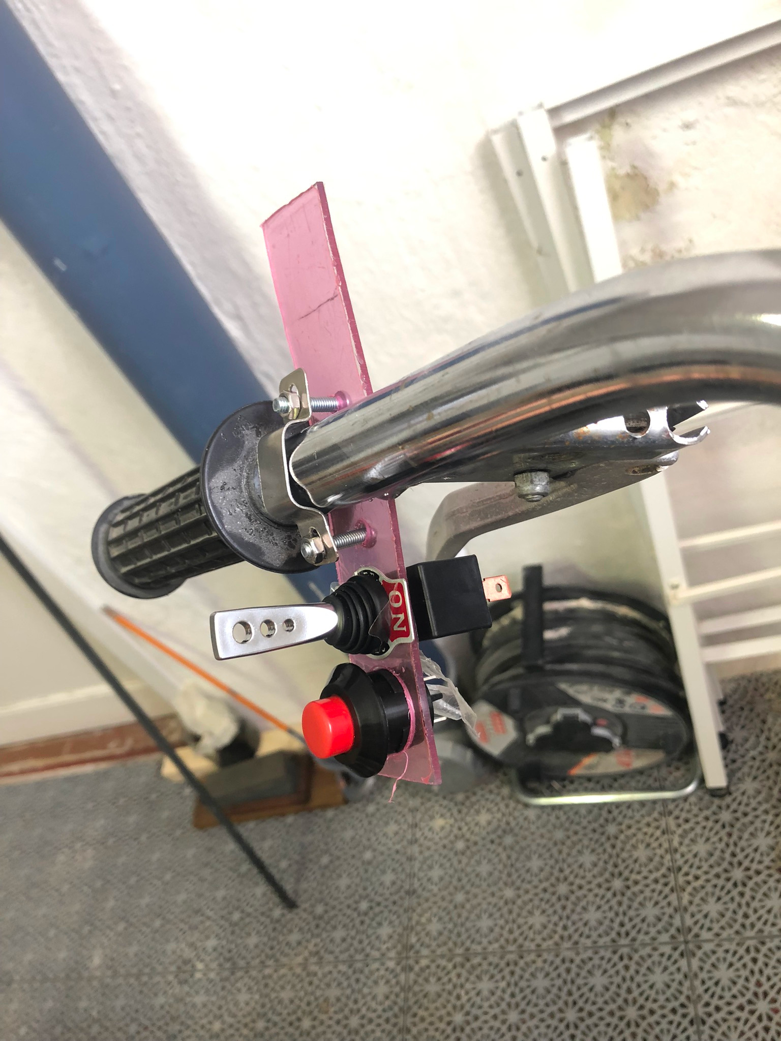
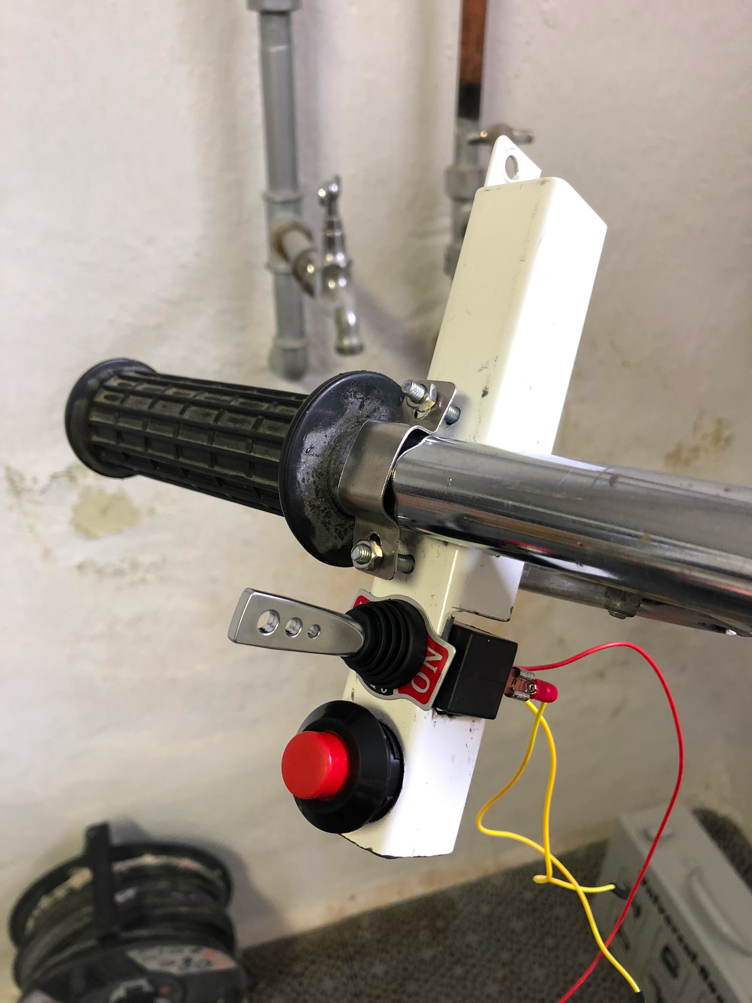
So I bodged together a control cluster (because you guessed it, that was thrown out too).
Cleaned up some wiring..
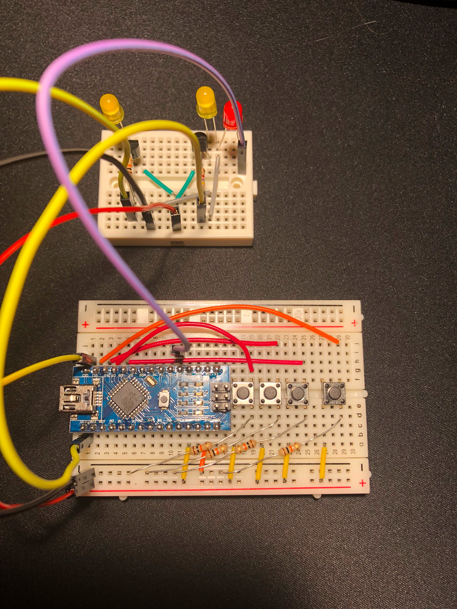
Created a mock control circuit
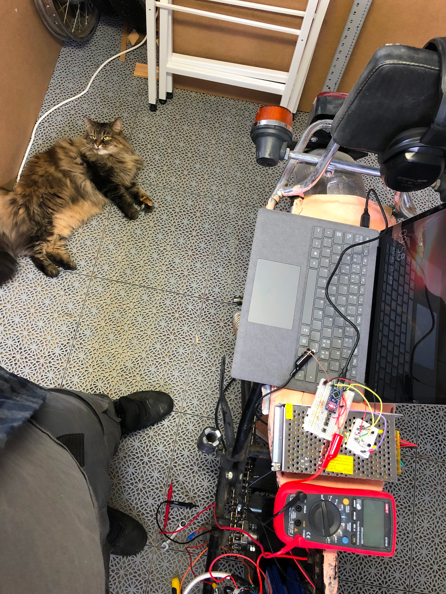
Programmed it under my trusty old workshop supervision
(I do clean quite zealously since she really loves hanging out with me down there)
Snapped the control cluster in half because 2mm acrylic isn't very strong.
So bodged together one from and old kitchen sink.
Happy to say that the logic works.
[youtube]https://youtu.be/w1NSw7879Tw[/youtube]
I continued to hook everything else up electronics wise.
Back light house was a bit tricker because they shared a common ground and the MOSFET drivers control ground not positive voltage.
So the positive terminal of the break light is separated from the otherwise common +12V that the license plate light share. And then i PWM ground via the common ground just to not over heat them all. Positive voltage for the break light goes through the break pedal relay that came with the bike, that way it can light up independently and mechanically while still getting the PWM benefits.
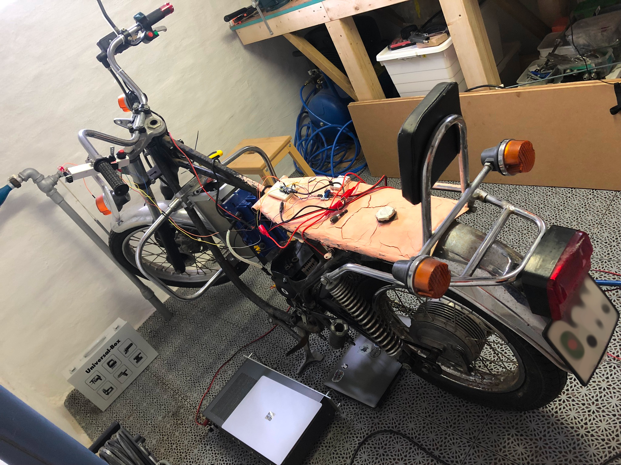
Refitted the rear tire as it was blown, will do the same with the front soon as the rubber is very old but still intact for a testrun.
And this is one of those moments when everything looks like it's coming together pretty well.
Added the 12V converter, and all the mosfet drivers on a little acrylic test piece.
And this is when the wiring mess hit me..
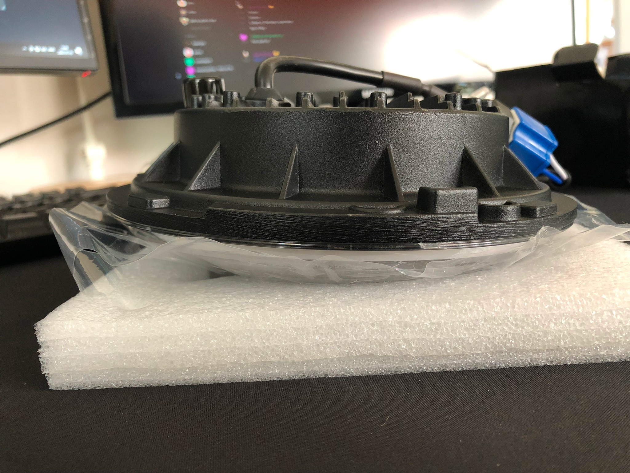
Luckily, the headlight arrived and got me distracted like a chipmunk for about 12 seconds.
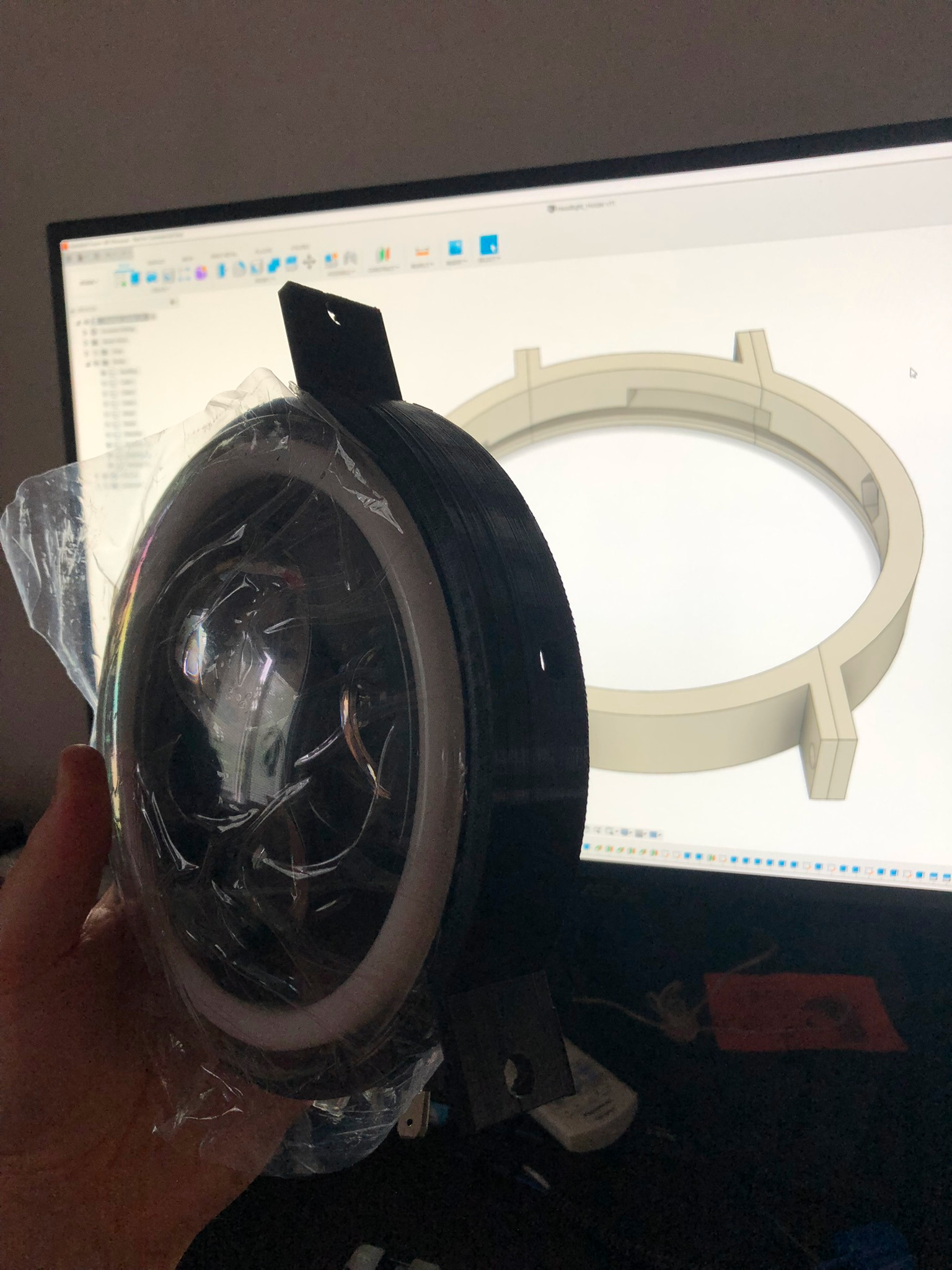
Until I found out that I know nothing about Jeep Wranglers and car headlight fixtures.. Apparently they use a trim ring to connect hings so there was no mounting holes on the headlight..
Fear not I thought, I'll make one.. two.. well three "trim rings" until I got one that worked.
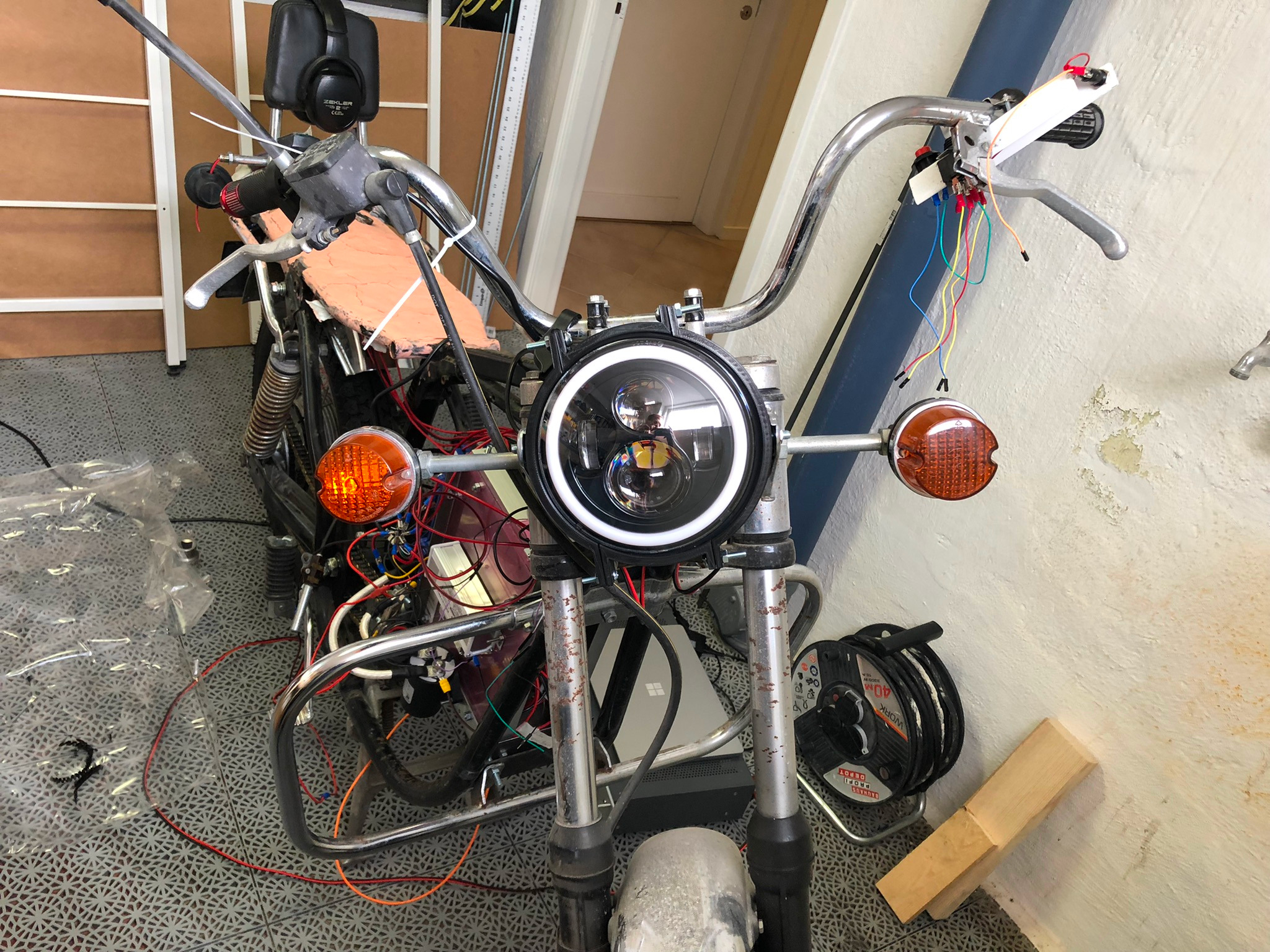
And it fit and looked pretty decent.
(Keeping with the theme of not being able to align a single thing, it's crooked but centered on the shocks at least)
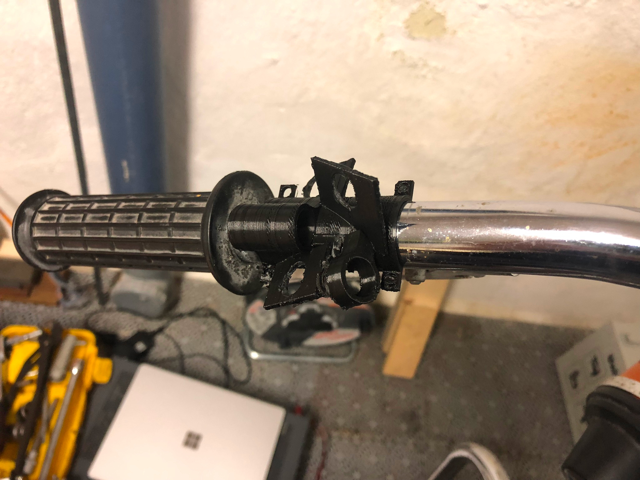
3D printed a new control cluster to get everything to fit more snugly.
Looked like garbage and was way to thin to support anything so did a second one..
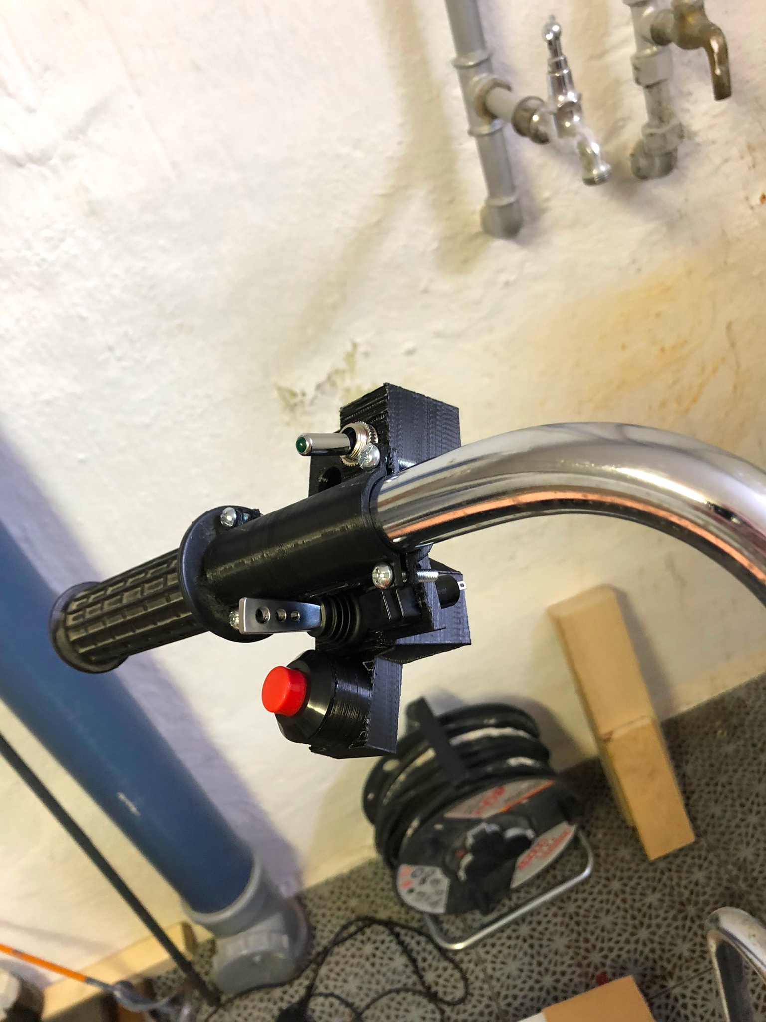
Turned out a lot better but had to re-do it a third time to get the screw holes sturdy enough.
Disappointed with my CAD skills in terms of mechanical strength I embarked on using Epoxy and fiberglass for the first time.
I've been putting this off for a long time due to smell, fear and not knowing what to do if I get it everywhere..
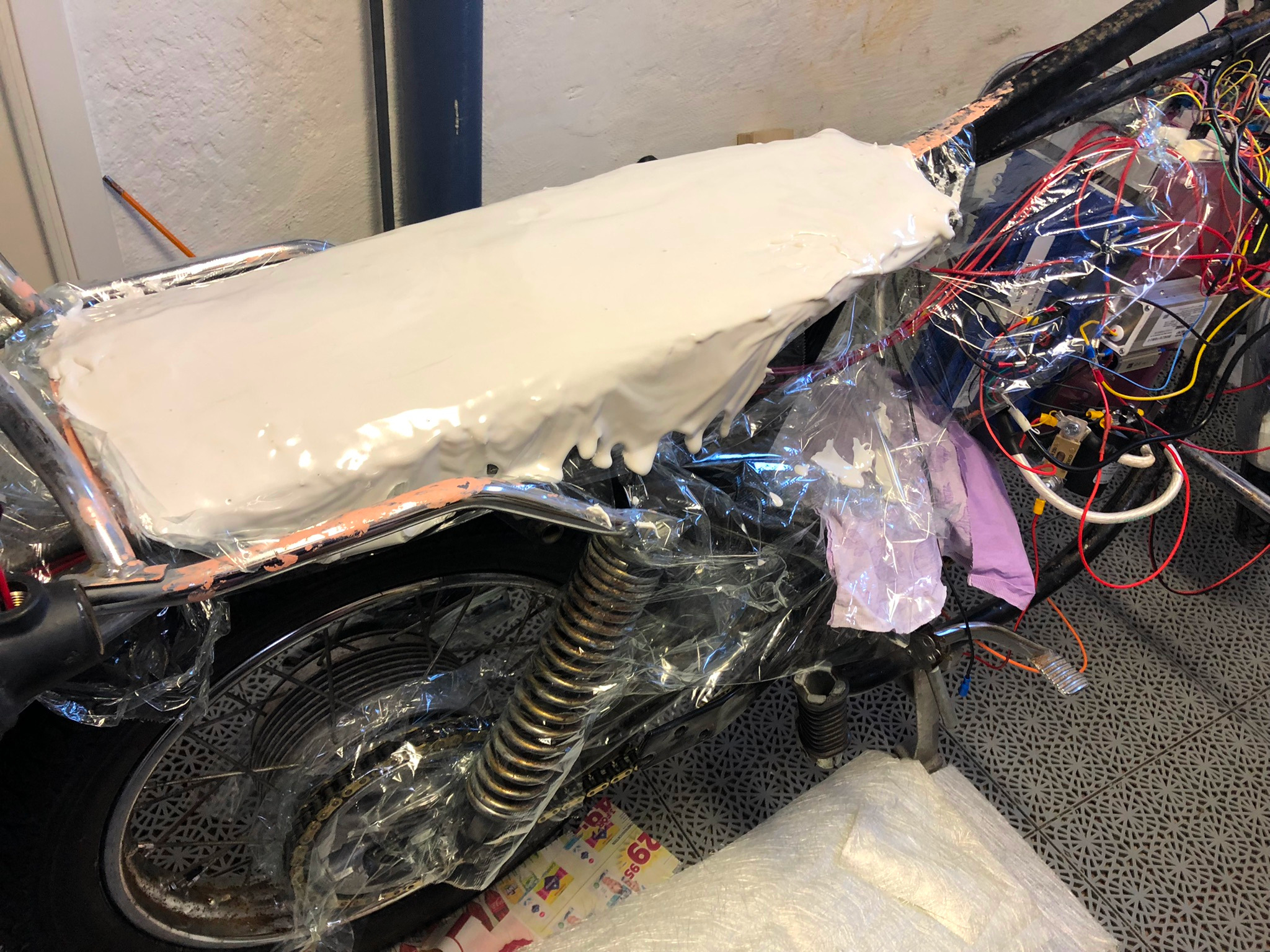
But I slapped on a thick coat of gel coat to get the contours right.
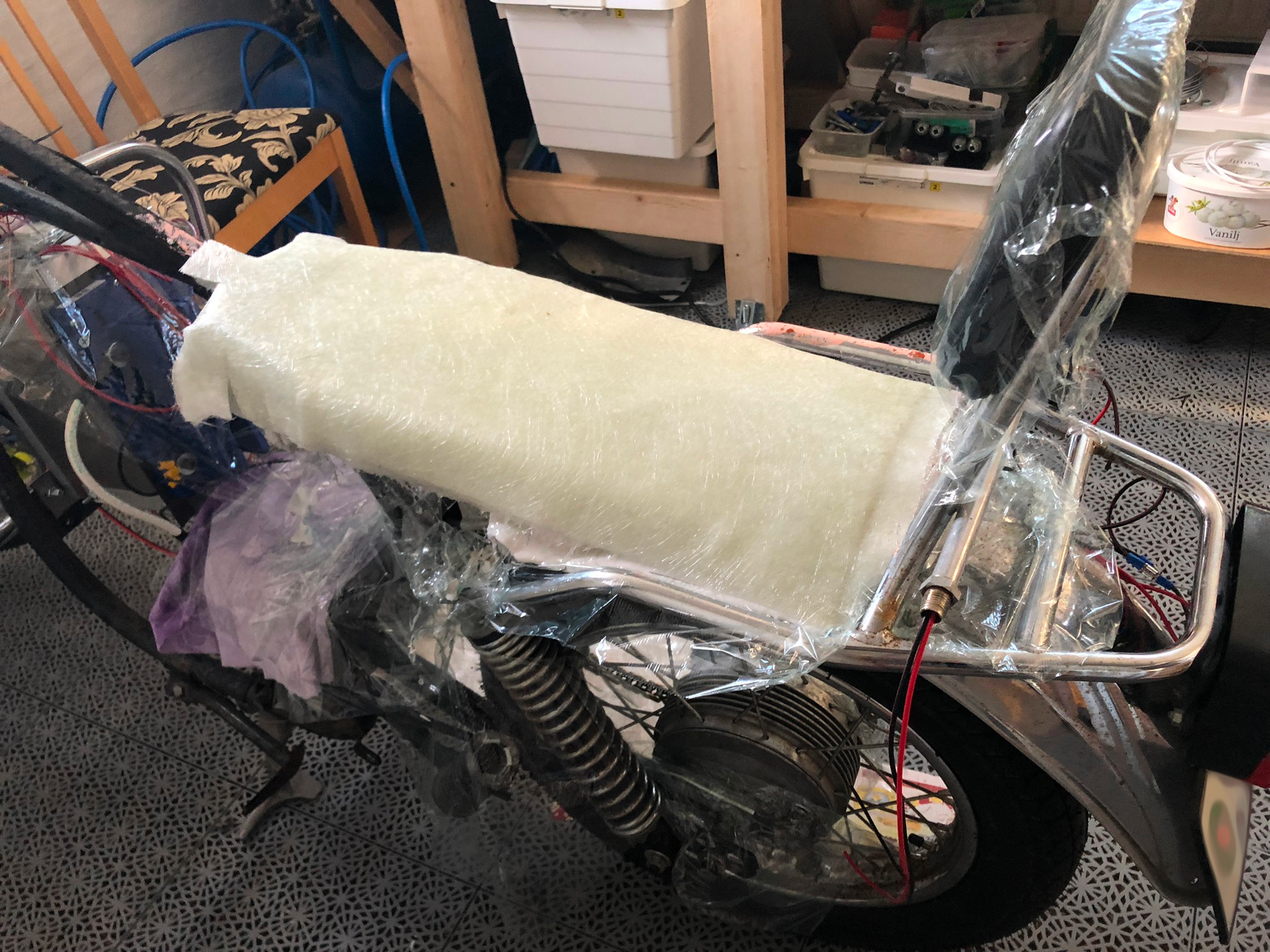
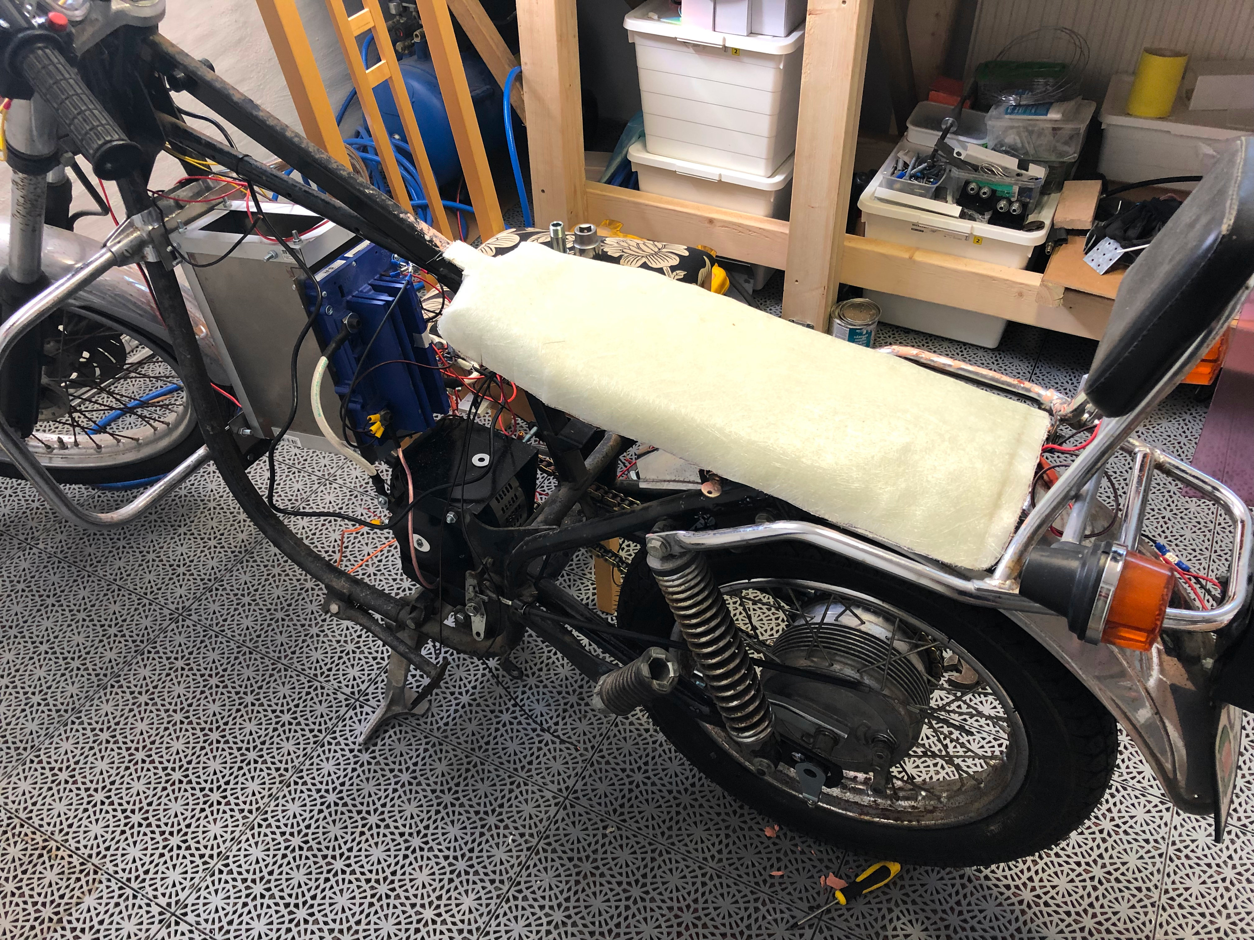
Let it rest for a bit, put some fiberglass on top and drenched it in epoxy.
And it turned out pretty good. After cutting it up.
Next up is upholstery, learning and failing there.
I also learned the other day that metric bolts and nuts have different thread sizes. There's fine thread and coarse threads.
Apparently the wheel shaft at the back wheel has a 1.5mm fine thread on a M14 bolt.. Not something that appears to be common as all nuts and bolts have a 2mm thread on them where I live. So I've ordered the most expensive nut I've ever ordered and while waiting for that to arrive, I'll youtube some upholstery stuff.
And that's where the project is as of today.
I'm out of vacation for 2022, but I'm hoping to get the rest done in the spare time before winter comes.
BMS is on it's way, should arrive within 2 weeks.
I know this has been a long post to say the least, but It's been my journey so far.
My goal with this is to learn as much as possible and maybe do more of these projects.
And to share back to the community what I've learned over the year or so.
Feedback is welcome, but keep in mind that I'm probably the greenest rookie on the forum. So be gentle