Spot Welding Battery Packs

crossbreak

1 MW
Joined
Aug 2, 2011
Messages
2,884
Location
Germany
After some request i now summarize the stuff i learned from schwibsi who built a nice welder and some others, using simple tools.. Posted my progress in his thread, which was a bit OT http://endless-sphere.com/forums/viewtopic.php?f=31&t=50015&start=75#p869087

..sry for that. Now here is room for discussion.

Some more notes:

Using car batteries in dangerous. The 200A fuse i built in DOES NOT PROTECT FROM SERIOUS GINGERY!! I always wear gloves and eye protection when welding.. i dont use it in enclosed rooms and have a fire extinguisher right besides me. Dont blame me if something goes wrong.. i made a lot of faults by my own.. i just post this so you may safe some of your time not doing the same errors as me


-If i knew where to buy cheap, i'd have used 6Farad of caps as power source instead of used car batteries. Sadly Caps are expensive. I would have spend ~150€ for the Caps alone at the bay.
-the arduino code is very rudimentary.. wrote that down in a few minutes.. a lot of room for improvement
-the batteries are not well connected. If I would have gotten a 120ah or bigger one, then i would not have used two small ones but one large instead


crossbreak said:
cool schwibsi. i'll try that as well, using old car batteries i got almost for free (2x Bosch 12/54ah with 560A peak in parallel 1120A ). I have 200pcs of the Sony VTC4 laying on my desk, ready to be wired... wanted to solder but know i wanna give this a try.

I'll have to find a source 6 of for the IRF1324 Fets. any idea? I could also use irfb3077 i have laying around... but i would need at least 12 since they have 2.8mOhms RDSon :(

Where did you source your irf1324? here in Germany?

I'll use the MCP1407 as a driver (with 100ohm resistors to the FETs :D ) , sound reasonable. Did you use multiple of these?

schwibsi said:
Voelkner/Conrad has both, the fet driver and the IRF1324.
DON'T solder the Sony cells.
The fet driver is bad-ass. Just one is required for all 6 fets.

crossbreak said:
i tried that already. google sux. thanks! Ordered 6 and a driver for 25€, that's reasonable. With arduino pro mini (8€) a foot button (1€) 1602 lcd (€2.50) some more Buttons, resistors and caps this project will stay below 50€. I think about using an Arduino micro or Attiny 861 instead to be able read a shunt in Diff-Gain-mode to be able to get a guess of the amps an joules that flow. But maybe i just dont need.

DON'T solder the Sony cells.
I soldered 2 to makes some tests. Got 2.2 - 2.25 ah @ 10amps from 4.22V to 2.7V, restance 17-18 mOhm. Good value IMO. I was very careful when soldering, but it was quite some effort. Welding seems so much easier.

schwibsi said:
It's not just that it's easier.
By soldering on the poles, you heat up the cell chemistry and thereby damage it. As you don't always solder the same, you'll damage them to different degrees, and they will have less life-time or not be drift-free anymore. I would steer clear of solding the cells.

schwibsi said:
I would use copper or tungsten for the electrodes and PTFE for the holder.

crossbreak said:
my solder tips always melt on the nickel plates... what do i do wrong? Too little current? Tried it with 25ms duration with solder tips as electrodes and a lead acid battery that does ~500A

Edit: The used solder tips are very cheap ones made of a Zinc alloy. Thought they are always made of Copper.. they are not.

I have a paralleled two 40A fuses at the positive wire to protect from short circuits. I'll try a 200A ANL fuse next +a second battery in parrallel. Have you tried wolfram electrodes? Found 4mm dia ones of 99.99% wolfram here http://www.ebay.de/itm/Wolfram-Elek...t=Schweiß_Löttechnik&var=&hash=item1c2f87d955

Hope the wolfram (melts at 3420°C) wont melt on the nickel (melts at 1450°C). It also is a better thermal and electric conductor than nickel.
file.php

the SMD gate driver failed after ~500 cells. I use the PDIP version now
file.php

This fuse failed, it works with 200A ANL fuse now.
file.php

tungsten electrodes failed, now it works with 5mm diameter copper electrodes that are being hold with one hand each
file.php

file.php

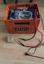
After some time using it, i put the stuff into a beer box with some foam to fit the 2 car batteries
 

Attachments

  • P1010653.JPG
    P1010653.JPG
    144.7 KB · Views: 15,673
crossbreak said:
BTW dont laugh about the tiny mcp1407 i used.. just got no other at völkner. i'l swap it for a pdip one as soon as I order from reichelt.

The arduino nano could be swapped for a cheaper attiny25 or 861 with fancy 1602 LCD but i had the nano at hand and it is so easy and comfortable to use.

Thx for the parts you suggested.. so for they work, besides the minor issues i have due my setup with the lead batteries.. for all who wanna built something equal here is my code.. it should run on a tiny as well.. you just need to change the button pin 7 and fet drive pin 5


Code:
boolean BtnWasPressed;
unsigned long BtnOnTimer;

#define DebounceTime 50
#define BtnPin 7
#define Fet_Driver_Pin 5
//#define Fet_Driver_Pin 13

void setup() {
  
  Serial.begin(115200);    // Open serial communications over USB
//  
//  for(int i=1; i<Fet_Driver_Pin; i++){
//    pinMode(i, INPUT_PULLUP);
//  }
//  
//    for(int i=Fet_Driver_Pin+1; i<13; i++){
//    pinMode(i, INPUT_PULLUP);
//  }
//  
  pinMode(BtnPin, INPUT_PULLUP); // Pullup for Putton Pin
  
}


void loop() {
  
    // check OK button
  if (digitalRead(BtnPin) == LOW)  {     
    if  (BtnOnTimer == 0) {
      BtnOnTimer = millis();  
      BtnWasPressed = true;
      Serial.println("BtnOnTimer == 0");
    }
    if  (((millis() - BtnOnTimer ) > DebounceTime) && BtnWasPressed == true ) {  // für entprellen 50ms warten 
      BtnWasPressed =false;
      weld();
    }
  }    
  
  else if (digitalRead(BtnPin) == HIGH) {
    BtnOnTimer = 0; 
  }   
  
}

void weld(){
  digitalWrite(Fet_Driver_Pin,HIGH);
  delay(2);                      // Weld impulse time 1
  digitalWrite(Fet_Driver_Pin,LOW);
  delay(40);
    
  digitalWrite(Fet_Driver_Pin,HIGH);
  delay(10);                       // Weld impulse time 2
  digitalWrite(Fet_Driver_Pin,LOW);
  
  delay(200);                      // Cool down time before next Weld
}


schwibsi said:
You probably need more current and shorter welding times. The target should be 3-5ms. After that time, you should get a decent welding spot.
If you don't the current is not sufficient.
The soldering tips probably melt because of the excessive heat due to the relatively low current and the long welding times.
Stronger power supply, thicker wires, better connections, faster switching and better electrodes (copper or tungsten) are some tings to look into.
To be honest, as I'ver said before, unless you want to do this regularly, it's not worth building a spot welder. It takes some tweaking to get this to work reliably.

crossbreak said:
ok thanks. the welder is well below 30€ ATM.. was fun to build. Guess my power source is sufficient, i think i just have way too much resistance in the wires connectors and fuse i use.

crossbreak said:
Now it works.. this is what i changed:

-Use single electrodes (one for each hand)
-use 200A AML fuse instead of normal 2x40A car fuse
-use 25mm² AWG3 cables instead of 10mm² AWG8
-use better battery clamps
-solder electrodes to cables, instead of bolting
-use copper electrodes instead of tungsten/wolfram (made of 4mm dia copper wire)
-decrease weld time from 20ms to 7ms

I tried about 100 times now and all spots are really good. I can not separate them anymore even when pulling hard. If I pull too hard, the spots simply break out, leaving a holes :shock:

here is a pic of my final setup.. thx again for your help!!

file.php

The middle 5mm of the cathode should be left out, since here is the foil connection inside the cell (bad example picture here)
file.php

schwibsi said:
The welding time still seems to be a little too long.
You should definitely not weld "through" the cell casing and the tape should not desintegrate either. Otherwise. you're running the risk of leaky cells.
 
crossbreak said:
yeah thanks. I see if I weld through one nickel plate alone i actually burn through, burning holes. I will try 4ms. BTW i use the rather thick 0.3mm nickel... so i thought a bit longer may be fine
schwibsi said:
Burning through the tape can also come from having too little surface area between electrode and nickel tape.
You want very little resistance between the copper and the nickel (therefore bigger surface area between electrode and tape), so that the heat is not generated between the electrode and the tape but between the tape and the cell. You're just heating up the cells unnecessarily. The electrodes and the tape should not burn.
crossbreak said:
yeah, that is why i use one electrode in each hand now. With both electrodes in one hand the pressure is not high enough, so it sparks... which leads to burned through holes. Also the electrode may not be too spiky.. it must be rather round. will practice more with dead cells before i actually start welding a pack.

Also i will try a smaller 125A AML fuse for safety. It seems that current is high enough now.. that was my major problem ... Now that this problem is solved i can do more fine tuning

Edit: 4ms weld time does just fine... the electrodes are not black anymore but the weld spots are still good...best thing: The electrodes dont not melt on the nickel no more at all :shock: now I want thicker electrodes since i am quite impatient and do 1 spot per second... which leads to hot electrodes quickly :lol: The FETs stay very cool.. can't even feel that they get warm
 
Exceptional work!
Best and cheapest DIY spotwelder design award goes to Germany. :mrgreen:

Is the gate driver implicitly requied?
The Arduino can deliver 40mah on the digital pins and the IRF1324 have Vgs 2V means they should turned fully on with 5V.
 
Ah many thanks!! yep the 5V wont be enough to switch fast enough ... acutally i do use only 82Ohms on the FETs now to switch them even a bit faster..it was an improvement over 100Ohm (i think).

This setup is really minimalistic so i made it as well as I could...with limited skills..and limited funds

EDIT: but i dont wont to burn my €15 FETs.. this is more than 50% of what I spend on this :lol: The MCP1407 can deliver more than an amp so...40mA WT!??? simply wont work without.. i use 82ohm / 6 = 13.7... so..that is almost an amp @ 12V i use
 
OK than i will try it and report here when i have finish'ed :mrgreen:
From what i have read FETs will only suck much mA when switched realy fast like in a controller with multi kHz.

Edit: 40mA for 1 pin. I can use 5 the same time for 200mA max. and i will try 200ohm with 5 FETs (wish me luck :lol: )
 
Great work, and thank you for the writeup. Will have a closer look in a couple of days and see what questions arise.
 
Hi Everyone,

I finally built a spot welder following crossbreak's own build.

IMAG1181 (Custom).jpg

There is still lots to be improved but it works.

Instead of arduino I used an Attiny85. The mosfet driver is the mcp1407 and the mosfets are IRFB7340, I only used 5 of them because that's what I had availabe, otherwise I would have used more.

As you can see from the picture, I use two little power supplies, one at 5v for the Attiny and a 10v (but it's more like a 12v) for the mcp1407.

IMAG1182 (Custom).jpg

This is the code I used on the attiny. Please note that this code is just an example, the values of delay are not correct (I still have to find the right ones for me). I am not using the second pulse as well.

Code:
unsigned long last_time = 0;
const int buttonPin = 2;     // the number of the pushbutton pin
const int mosPin =  0; 
int buttonState = 0;
int previous = 0;
int count = 0;
void setup() {
  
 
 // initialize the LED pin as an output:
  pinMode(mosPin, OUTPUT);     
  // initialize the pushbutton pin as an input:
  pinMode(buttonPin, INPUT);
  
}


void loop() {


  // read the state of the pushbutton/footswitch value:
  buttonState = digitalRead(buttonPin);


  if (buttonState == HIGH && previous == LOW && millis() - last_time > 250) {    // debouncing for footswitch
       
   
    count ++;      // add 1 to the count
  last_time = millis();  
  }
    
    if (count == 0) {
      digitalWrite(mosPin, LOW);   // turn the LED on or actually close the MOS in this case.
  
    } 
    
    if (count == 1) {
      
      digitalWrite(mosPin, HIGH); 
    delay(500);               //mosfets stay "closed" for this amount of time in ms. You need to adjust this depending on your needs and/or setup
    digitalWrite(mosPin,LOW);
  delay(400);               //Cool down or pause time before next weld
    
 // digitalWrite(ledPin,HIGH);  //This is for second pulse, not used in my project
  //delay(500);                       
   count ++;
  
    }

if (count >= 2) {
      count = 0;
  }

}

I don't have a schematics yet but I will see if I have time to draw something in the next few days.

First decent weld (after the failures using the SCR and thinner cables):

IMAG1184 (Custom).jpg

I am going to work on the code and find a decent power supply for the capacitor to improve the weld.


Edit: updated the code with comments and deleted garbage stuff used for testing.
 
Here is the schematic of my board. I simplified the mosfet part. They are all in parallel and I use 1 gate resistor (1k) and 1 pull down resistor (10k) on the gate in total.

Attiny85SpotWelderB.jpg
 
riba2233 said:
Can you take some more pictures of your welds? I hope that this burned area was from previous, unsuccessful attempts. :mrgreen:

Welds are getting better. The burned area is from the previous welder with the SCR and 10AWG cables...I was making big holes and no welds...Now it's much better.

IMAG1191 (Custom).jpg

In this photo there is an unsuccessful weld as the cap was not fully charged. the other welds are strong :D
 
Great work spuzzete and cross break!

A spot welder at my disposal would simplify pack building a lot.

spuzzete, are the red and black wires coming off of the cap used to connect a car battery? could you show a photo of the battery? what specs does it have?

the cap is 1+ farad? do you have the exact spec and price for it? where did you get it, or was it just something in your parts box?

Thanks for sharing your work!
 
Thanks Silentflight.

Crossbreak uses car batteries and NO cap.

I use a power supply AND a cap. The approach is different. The system works for both but you will have to change some stuff (arduino/attiny code for sure).

I used a rockford fosgate capacitor 1F, bought on ebay for about 60-70$. As a power supply I still have to find the best one.I have been using a 3s2p sony konion pack with a power resistor (1-3ohm 30-50W) is series on the + to the cap to charge the cap slowly. I also used and ATX power supply and a laptop power supply (but the voltage is too high).
 
Thanks for your reply,

How long do you need to wait between welds (while the cap is charging up again)?

What are you using to actually make the welds- are they copper rods? Any info on where to get them?

When I think about building a pack I often wish I had a spot welder, so this thread is fantastic, especially as I enjoy diy and arduino projects. This seems like a perfect topic for the sphere!

Do you think your welds are about as good structurally/mechanically and electrically as an off the shelf spot welder?
 
You guys do know that there was a huge thread on this topic here a few years ago, don't you?
http://endless-sphere.com/forums/viewtopic.php?f=2&t=2633
 
Yes but I was able to find only partial info. Reading 1 page with the correct info is much easier than reading 40 pages and try to guess what is the best way to build a spot welder .
 
Shortened the electrodes and put everything in a box. Now using a 3s2p sony konion pack with a 1ohm power resistor to charge the cap (1 second) and it works beautifully. I am practicing and getting better with the welds.

I ordered a voltmeter to see the cap voltage and will put on a relay to disconnect/connect the battery pack to the capacitor. I will also build a little circuit to discharge the capacitor after the last weld.

IMAG1192 (Custom).jpg
 
A little teaser, my version with pic. Basically the same as spuzzete's, but with PIC micro controller.

Question for spuzzete - are you using only one 1k resistor for gate driver? Like one for all mosfets? Also what mosfets are you using exactly? Because those noted on your schematics doesn't exist :)


0S7hHZ1.png


Picture is lacking solder mask and some silk screen values.
 
Back
Top