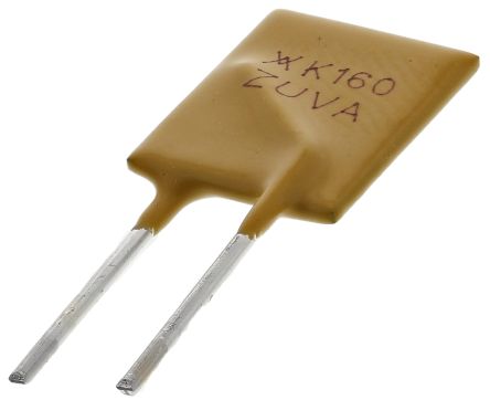
This here fuse looks like it would cut things off prior to the wire vaporization though?
Probably, but it depends on the current created during such a short--if only two balance wires shorted on cell groups right next to each other, it might be low enough to not cut the current. You'd have to make sure, like the second post in the thread implies, to pick one that will trip on the mildest current that you want to protect against, but *not* on any actual desired current.
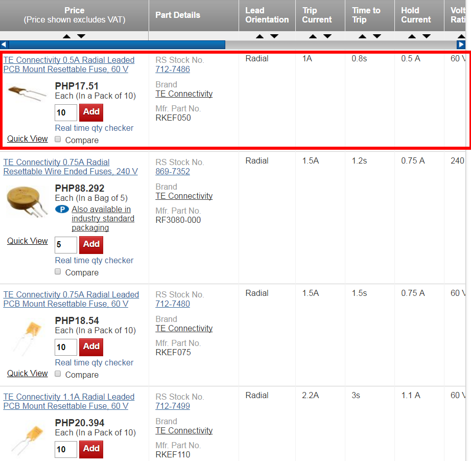
Balancing currents are typically in the few dozen mA range at most (some BMS are much less than this), so check what yours can do and pick a PTC that is rated for just that amount or a tiny bit more, but that according to it's spec sheet *will* trip on the lowest current you might see during a shorting event to the next cell group over.
The next cell group over will be at most 4.2v difference for the lowest-potential short, or 8.4v for the highest-potential short. The least difference would be whatever the LVC on your cells is in the BMS. To find out the least-case short current, you take that least difference (probably 2.8v?) and divide it by the resistance of one full parallel cell group, which would be the resistance of the balance wire plus that of the interconnects (both probably negligible), and that of the cells themselves at LVC (cell resistance divided by the number of cells in parallel--so if they are say, 100milliohm at that voltage, and there are four in parallel in the group, that's 100 / 4 = 25 milliohm cell resistance. Round it up to 30 to include the wires/etc if you like. (but you'll need to look at the cell spec sheet or testing data to find out it's resistance at LVC, which is different than the average resistance published for the cell in it's spec sheet (though you can use that if you have to).
So in that example, 2.8v / 30milliohm = 93.34amps. Meaning the PTC would be required to trip "instantly" below that current (preferably below the current at which the balance wires would begin to be damaged), but *not* trip at the balancing current itself (call it 50mA unless your BMS has a different spec).
How would one go about wiring this into series with the balance wires? I can't quite wrap my head around it...
That is the simplest part--you disconnect the balance wire from the cell, and connect it to one leg of the PTC. The ohter PTC leg connects directly to where you disconnected the balance wire from so the PTC is actually at the cell or cell interconnect, with no wire between it and the cell/interconnect, since it is there to protect the wire you don't want it to have any unprotected wire. .
Mounting the PTCs so they won't have legs break off from stress or vibration, or short to anything, is a good idea.


 lots of heat and smoke, vaporized wire but no fire and the batteries are all testing at the proper voltage. BMS appears to be functioning just fine...