Meanwell HLG-320H-54A + ignorant battery design questions.

fourbanger

100 W
Joined
Jul 17, 2014
Messages
214
Location
Vancouver B.C. Canada
Hi guys. First off, I just received the afore mentioned meanwell led driver from digikey for $130 Canadian pesos (super fast delivery time, btw; highly recommend) but the thing seems to max out at 58.7VDC. My question is will the 0.1V deficit give me problems balancing a 14S system using a cheapo BMS, or will it be close enough to activate the balancing function.

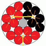
My other questions are regarding the battery design its self. I am attempting a cylindrical design using a 4" sewer pipe and would like to incorporate cell level fusing. I've attached a high quality MS Paint artist's rendition of what I've come up with. The yellow lines represent 12awg stranded wire, the orange lines represent individual strands serving as parallel connections. Each individual strand measures approx. 0.47mm [EDIT: 0.44mm] which I'm hoping will allow for a blow out at around 20A or so. Each set of 3S6P groups will be separated by 1/4" soft white packing foam. I'm not looking to draw more than 30A from this pack. Will this suffice, or will those little strands get too hot?

Also, I'm curious as to why people are inclined to beef up their series connections at the + and - output terminals of their battery packs? Shouldn't a current draw of 30A simply be 30A across the board for example?

Looking forward to hearing any advice, reference material or anything else that might help to un-stupify myself.

Many gracious thanks in advance.
 

Attachments

  • spsr_rev1.gif
    spsr_rev1.gif
    31.9 KB · Views: 1,024
fourbanger said:
My question is will the 0.1V deficit give me problems balancing a 14S system using a cheapo BMS, or will it be close enough to activate the balancing function.
Balancing is generally done by each cell's channel, so it isn't really the total pack voltage, but rather the individual cell voltage that the BMS itself is designed to start balancing at. (though the total voltage makes a difference as to whether under normal conditions most cells would ever reach the balance point).

So if the BMS is made to start balancing at 4.20v, and a cell is out of balance at 4.21v, the BMS will do what it needs to to bring it down to whatever the balance cutoff voltage is.

The other cells that are lower than that won't balance, but since they are lower, they don't need to.

If any of them are really low, then their voltage difference will be spread among the other cells as it reaches full charge, so those that go over the balancing point will be drained down while the charger continues to fill the low cells, until they are all near or at the balancing cutoff voltage.


If none of them are low enough to give enough voltage headroom to other cells during charging, no balancing will likely occur, but that also means that none is needed (they're all really close to the same voltage anyway).
 
58.7v will be close enough. The accuracy of the BMS shunts isn't that great either.

Your wiring layout seems OK. Heavier parallel connections on the ends is to help even the current draw on all the cells.
 
Nice. I knew I'd get some intelligible answers here.

I am using new pink cells from nkon. 35E.

Amberwolf, your answer is by far the most detailed and by far fills in the most blanks as to how a BMS actually works. I can't help but feel that the best option for me is simply to have sense wires available and check the parallel group voltages myself. It's a pity they don't make battery medics that'll read 8s like the cellogs. That'd be pretty sweet.

Fetcher, I thank you for the thumbs up on the overall design. I was a little concerned that the parallel fuse wires might get hot enough under normal operation to melt through the foam packing. I'm still not sure I entirely grasp the concept of your last sentence; "Heavier parallel connections on the ends is to help even the current draw on all the cells."

Would any of you mind pointing me in the direction of some reading material (pictures are nice too) that might help clear that up for me.

Thanks a million guys. There's a lot of contradictory/conflicting information out there, and it's really nice to just ask a few guys who sort of just know right off what I'm trying to get at.

Cheers.
 
fourbanger said:
Also, I'm curious as to why people are inclined to beef up their series connections at the + and - output terminals of their battery packs? Shouldn't a current draw of 30A simply be 30A across the board for example?

I was attempting to answer this question, but perhaps I misunderstood. If you have a parallel groups connected in series where each cell has a series connection to the next group, then the parallel wires carry very little current, except at the ends. At the ends, the current from all the cells in the group has to be concentrated down to a single wire. By using an extra heavy parallel connection on the end, the current sharing between cells will be more even. This is more of a factor when using nickel strip to connect the cells due to the higher resistance.

In your layout, essentially every group is concentrated to a single wire, so that wire needs to be heavy. Due to the cylindrical package and the arrangement of the cells, it's hard to configure them otherwise. As long as all the conductors are heavy enough, current sharing will be good.

Making sure none of the wires heat up is important. You may want to test before you build. You don't want a safety feature to cause a failure. Personally, I would sacrifice the fuse feature and just use heavier wire and an actual fuse somewhere in the pack. If you manage to cook off a cell and it starts burning, the fuses won't stop it.
 
Thank you for posting that design layout, I'm working on a similar project.
How tight is the fit inside the pipe and would there be space enough to put a 1/8 inch thick foam insulator between each of the three "blocks"?
I always try to add an extra layer because I don't trust the thin wrappers on the cells.
I have also had good results using sections of 1/2" CPVC (hot water tubing) as space holders when there is an empty spot like in the center of your design.
Good luck and please post your progress
 
https://endless-sphere.com/forums/download/file.php?id=98636

Fechter, I kind of think I know what you're getting at, having remembered this guide. It occurs to me that "low power" was never really defined, but I still feel that cell level fusing is the way to go

Hwy89, thanks for the tip on the 1/2" tubing. A business card of reasonable quality separates the parallel groups nicely. I don't trust that shrink wrap either.

P.S.

The notion of a safety feature causing a failure is exactly the kind of tragic irony I'm trying to avoid, yet seem to be irresistibly drawn to.

I'll start a new thread to keep you posted.

Thanks again, gents.
 
Tesla uses cell level fusing, so there must be some advantage to it. Just keep in mind the fusible links might get hot enough to melt the cell wrappers, so you need to insulate with Nomex, fish paper or something that won't melt. You can also make the fusible part as short as practical so you don't have any more heat generation than necessary. The fusible parts may also be susceptible fatigue fractures, so both ends need to be attached to something that won't move.
 
Back
Top