S-LCD to S12S controller communication protocol hacked

obelix662000

1 µW
Joined
Oct 13, 2015
Messages
4
I've successfully decoded communication protocol between LCD3 display and S12S controller (both available at bmsbattery.com) in both directions. Please see attached files.
 

Attachments

  • S12SN_to_LCD3.txt
    1 KB · Views: 4,535
  • LCD3_to_S12SN-1.txt
    2.6 KB · Views: 3,431
flangefrog said:
Great work. When were the packets sent between the devices? Were they sent every 100ms or so, or for lcd to controller communication were they just sent when a button was pressed? Any special packets sent on start-up?
Continiously, about 10 times a second in both directions. Actually this is not important, everything works fine with any rate since LCD an S12s rememeber last state.
 
obelix662000 said:
I've successfully decoded communication protocol between LCD3 display and S12S controller (both available at bmsbattery.com) in both directions. Please see attached files.

Do you know if the controller will transmit the package without the LCD hooked up?

I'm trying to program my S06S ( which I presume to be similar ) with out the LCD as a "project" since I forgot to include the LCD in my last order from BMS. I have attempted to read its TX line at the settings described and did not get any output. Help eliminating the unknowns would be appreciated.

Thank you very much for your work so far.
 
In addition to the above, i found out the following:

I have an S06S, the protocol is the same.
Regarding the S12SN to LCD3 communication protocol:
B2: is the controller voltage. I have a 24/36 V controller with a 36 V battery and B2 reads 36 in my case.
B6: B0 is not included in the CRC
B8: Value is 4x controller current instead of power. The display calculates the power from this value devided by 4 multiplied with the LCD supply voltage. So if B8 is 16 and the supply voltage is 30 V then the LCD shows (16/4)*30 = 120 W. If you supply the LCD with 40 V and the same value for B8 then the power shown is 160 W.
 
For the LCD to controller protocol, the crc in B5 is not always as described here, at least for my LCD5 and controller, both recently bought from bmsbattery.

The final xor 2 required in the crc calculation varies, even for exactly the same message but at different sessions/times - sometimes an even number in the final xor is required and sometimes an odd number.

Rather than attempt to work out how or why, I simply find the correct value from the first few messages sent by the LCD after powering on, and use that for the remainder of the session until the LCD is turned off.

If you're getting messages you're generating ignored by the controller, bear this in mind. I've recently added an arduino to dynamically modify the parameters (max speed / assist levels / etc) when in an internally managed "fast" mode set with a sequence of LCD buttons at startup, and this stumped me for a while, particularly as sometimes xor 2 is the correct value and so sometimes works.
 
jbs said:
I've recently added an arduino to dynamically modify the parameters (max speed / assist levels / etc) when in an internally managed "fast" mode set with a sequence of LCD buttons at startup, and this stumped me for a while, particularly as sometimes xor 2 is the correct value and so sometimes works.
Hi guys.

This thread is really valuable!! I just shared all this information on the OpenSource firmware for the BMSBattery S Series / Kunteng KT motor controller documentation page: https://opensourceebikefirmware.bitbucket.io/Controllers--BMSBattery_S06x--LCD_control_panel--LCD_protocol.html
 
Can you please please help me to understand:

"B3,B4: speed, wheel rotation period, ms; period(ms)=B3*256+B4;"
"P1 = motor gear reduction ratio×number of rotor magnet pieces, just rounding if there’s any decimal."

Considering: 1 eRPM at each 2 rotor magnets;

B3B4 = P1 * (eRPM / 2) ??
 
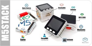
I just got one of these M5Stacks to play around with.

C4zBP0jUYAEZbbl.jpg


Though they are not specifically for an Ebike, they are fully programmable, bluetooth / wifi.

Seems to me that they could be a good candidate for an LCD meter.

They cost $16 + postage (about $4).

Im going to see if I can interface mine with the controller using the serial protocol top of this thread...
 
I am trying to control BMS battery sinewave bottle controller in a similar way with an ESP32.
The UART on the ESP32 allows only for 3.3V input and output voltage. What are the voltages levels on controller and SLCD?
If they are 5V, what would be the easiest way to convert?
 
MisterMint said:
I am trying to control BMS battery sinewave bottle controller in a similar way with an ESP32.
The UART on the ESP32 allows only for 3.3V input and output voltage. What are the voltages levels on controller and SLCD?
If they are 5V, what would be the easiest way to convert?
BMS Battery S/Kunteng controllers work with 5V. You can see the schematic of the controller on our project site, OpenSource firmware for that controllers.

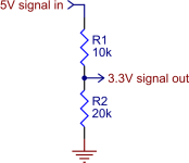
Voltage resistor devider from 5v to 3.3v, on the line from the STM8 to the ESP.
From ESP to STM8, keep that 3.3v that STM8 should be able to read correctly the values as 1 logic.
So, just 2 resistors to adapt!!

Can you please share what do you plan?? How will the user interact on your system??
 
Thank you for the info, i even be should be able hide this inside cable.
So it seems this is all I need:

z5AQJ.png

The project is still in early stage, did not even receive the ESP. I will try to control a 2WD bike via Smartphone. Seriously need fast 'mode switch', after this works, this is gonna be my playground for a while.. lights, brake sensor, distance sensor, alarm, anti-slip for front wheel, who knows where I will end. :)
 
MisterMint said:
The project is still in early stage, did not even receive the ESP. I will try to control a 2WD bike via Smartphone. Seriously need fast 'mode switch', after this works, this is gonna be my playground for a while.. lights, brake sensor, distance sensor, alarm, anti-slip for front wheel, who knows where I will end. :)
Okok, a lot of things you are looking for :)

Why not going with the standard UART/Bluetooth module for this motor controllers? On our project, we just started to add support for the LCD (which is the same for Bluetooth).

How do you plan to develop on ESP, which language? -- I am looking to JavaScript Reactive Native app for mobile.
 
I want to do all the computation in one place. It should be able to run in standalone mode.
Will run Arduino firmware for ease of programming, the GUI on Android phone will most likely be TouchOSC or Lemur.

I am really looking forward to test your custom firmware, but what you are doing right now is way over my head. So I will wait for working beta.
(I have some support from a friend to solve programming and electronical issues.)
 
MisterMint said:
I am really looking forward to test your custom firmware, but what you are doing right now is way over my head. So I will wait for working beta.
(I have some support from a friend to solve programming and electronical issues.)
I would like to understand what are the specific features needed for a 2WD -- can you please tell me?

So, I wish to have a firmware to make this controllers as a generic ones, that can be controlled by UART from Arduino or such, like sending commands to start the motor, running forward with max current of 10 amps and max speed of 30km/h.
 
The controller has already a 2.2kohm resistor in series with the uart lines, so a 3.9kohm on the TX line connected to ground is enough to have a 3.2V CMOS signal.
 
Can someone please help me understand how to calc xor 2?? I can calc xor ok, as I am already sending information with success to the LCD (and the motor now works pretty well as original firmware):

[youtube]6JcclC9Pod8[/youtube]
 
casainho said:
Can someone please help me understand how to calc xor 2??

You should just be able to perform the calculation given your value, depending on your programming no language

E.g. 10 xor 2 = 8

In c it would be x ^ 2 = result, e.g 10 ^ 2 = 8
 
jbs said:
casainho said:
Can someone please help me understand how to calc xor 2??

You should just be able to perform the calculation given your value, depending on your programming no language

E.g. 10 xor 2 = 8

In c it would be x ^ 2 = result, e.g 10 ^ 2 = 8
I got it and working, however that data I got from my LCD5, I had to do "xor 9" for having a correct CRC:
Code:
    // validation of the package data
    ui8_crc = 0;
    for (ui8_i = 0; ui8_i <= 12; ui8_i++)
    {
      if (ui8_i == 7) continue; // don't xor B5 (B7 in our case)
      ui8_crc ^= ui8_rx_buffer[ui8_i];
    }

    if ((ui8_crc ^ 9) == ui8_rx_buffer [7]) // see if CRC is ok
    {

[youtube]b5erBqISRE0[/youtube]
 
Sorry for the late reply, project got delayed for reasons.

@casainho: Why 2 WD?

Its the most stealthy way to pack some power onto a bike imho. Q100C and Q100H are really tiny & light motors, they don´t cry
"e-bike" from first glance, but if you keep watching the temps you can feed them around 1 kW for a limited time. Nylon gears will wear our for sure quickly, but this stuff is cheap. Once you manage to open your used motor you can even replace the gears by 3D printed ones: https://www.thingiverse.com/thing:2123772

One of them is already nice, running the Q100H 36V @ 48V 20A in the front right now. (I know, I most likely do magnetically saturate it, but it works like a charm..) Problem: You can easily kill it when its summer and you go up a long, steep hill. Been there, seen that. :roll:

Two of them should be strong enough to pull you up any hill without going below the magical 20 km/h - this is where efficiency on the Q100x 201 rpm versions really drop, which leads to quick overtemp.

Two light motors have better weight distribution than one large (even though I was not amused when I recognized the lower agility with such a heavy front wheel on gravel and the like - but I do not drive around gravel often..), and should also give better traction, as both wheel are "biting" into the ground. Last but not least redundancy is a good thing, when one fails you can still go home without hassle.

Time will tell if 2WD is really as good as I believe.. ;)

about the project:

So, finally I have second motor mounted (with torque arm), second controller modded to XT60, (really expensive) bare HIGO plugs and a small arduino which runs 5V TTL on my table. (ESP32 still sucks when it comes to use the internal Wifi/Bluetooth with Arduino firmware.).

My Higo Plug (with cable already attached) has 5 pins. The cable colors do not match with anything I can find on the net.
Looking at the male plug, counting from one to five clockwise, while the nipple is at the bottom I have following colors:

1: Red
2: White
3: Brown
4: Green
5: Black

Does anybody know what is what?
 
Blik86, thanks for the chart. I'm not able to view the spreadsheet properly on LibreOffice. Can you please explain what C4S and C4% are? Also what is L1?

Edit, found what C4S and C4% are referring to in the manual:
When C4 = 2 is confirmed, "specified speed limit value of handlebar" flashes, press (UP) button or (DOWN) button for short to make selection, and the default value is 20.
When C4 = 4 is confirmed, the "percentage value of the first gear speed accounts for its full speed" of the power assist gear flashes, press (UP) button or (DOWN) button for short to make selection, and the default value is 50%. The percentage values of other gears divide automatically in equal.
 
jbs said:
...
The final xor 2 required in the crc calculation varies, even for exactly the same message but at different sessions/times - sometimes an even number in the final xor is required and sometimes an odd number.
....

to compute checksum correctly, start with crc=0x0E, and not include first byte
Code:
    crc = 0x0e
    for i, v in enumerate(rxbuffer):
        if i != 5 and i != 0:
            crc ^= v
 
zlabs67 said:
The final xor 2 required in the crc calculation varies, even for exactly the same message but at different sessions/times - sometimes an even number in the final xor is required and sometimes an odd number.
CRC = (xor B1,B2,B3,B4,B6,B7,B8,B9,B10,B11)
 
Back
Top