Front wheel Friction drive

ferias77

10 W
Joined
Apr 25, 2011
Messages
74
Location
Bordeaux, France
I would like to try a friction drive on my recumbent.

At the moment, I use a Q100 36V 328RPM with a KU63 controler and a 48V 10Ah battery. But I would like to try something different and lighter.
My recumbent with the Q100 :
img-1090.jpg

I made 30 000 km with this motor. The controler is under the seat and the battery in the tail box.

For my Friction drive, I will use :
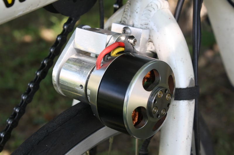
- Motor : Turnigy G110 Brushless Outrunner 210kv : http://hobbyking.com/hobbyking/store/__19039__turnigy_g110_brushless_outrunner_210kv_1_10_glow_.html
- Controler : S06P 250W Torque Simulation Square Wave Controller : https://bmsbattery.com/ebike-kit/545-s06p-250w-torque-simulation-square-wave-controller-ebike-kit.html
- Battery : 25,9V 10Ah (7S)
- Roller : 40mm diameter :

- aluminium bracket and swing arm

I will install the friction drive on the front wheel.

The friction drive working :


The drive out of the tire :


The drive in the tire :


What do you think about this design ?
I will add lower and upper dead stops.

I machined the roller and tried it no load on the tire : 37W and 43,3 km/h with 25,9V.
Now I am waiting for the aluminium to make the bracket and swing arm.


Edit : 26/07/2015

I began machining the parts of the friction drive :


Edit : 16/08/2015

The bracket is mounted on the bike :


All is very rigid. :D


Edit : 28/08/2015

The system is assembled :


And mounted on the bike :


Now, I have to add a spring loading the roller off the tire in the off position, and a endstop for the off position. And finally, to test it !!!!! :D


Edit : 04/09/2015

I made 207 km with my friction drive : 30.5 km/h average and 6.4 Wh/km. Motor and controler stay barely warm..

I have modified my S06P controler : 23A max instead of 14... :D

Before modifying the controler :


After modifying :


Edit : 23/09/2015

802km with the friction drive !

A photo of the complete system :


Mounted on the bike :


It works perfectly when it's dry. But it slips when it's wet.
I have to make a knurled roller, like EVTodd...
I replaced the friction drive with my Q100 hub motor, waiting for this knurled roller.
 
I like it, but why not use a solid piece of aluminum across the top of your bracket instead of two smaller pieces? It would be very easy to shim between the two plates for fine tuning or accommodating different tires.
 
My only concern about this design is the stiffness of the fork attachment.

gogo said:
I like it, but why not use a solid piece of aluminum across the top of your bracket instead of two smaller pieces? It would be very easy to shim between the two plates for fine tuning or accommodating different tires.
The aluminium part on the left is to prevent the rotation of the system.
And the aluminium part on the right can be rigged with washers to fit the geometry.
With only one aluminium part, it is impossible to have both functions, no ? :?
 
your design is flawed, the inertia from the motor startup will actually spin the roller away from the tire and it won't engage. You need to put the swing mechanism behind the steering fork.
 
maxchilton said:
your design is flawed, the inertia from the motor startup will actually spin the roller away from the tire and it won't engage. You need to put the swing mechanism behind the steering fork.


Lol. Only if he's riding backwards.
 
Kepler said:
Design is sound.
Dont forget to add endstop adjustment and a method of spring loading the roller off the tire in the off position.
Yes, I don't know how I will do it, but I will add it !

I began machining the parts of the friction drive :
 
ferias77 said:
Kepler said:
Design is sound.
Dont forget to add endstop adjustment and a method of spring loading the roller off the tire in the off position.
Yes, I don't know how I will do it, but I will add it !

I began machining the parts of the friction drive :
5-5.jpg

Looking forward to seeing it done. I've been thinking about getting a KMX trike for a rear friction drive. It's nice seeing a couple of new diy friction projects again. Much better than paying $1000 for a "commercial" one.
 
I don't remember if the motor needs to be on the left or the right, for the start-up torque to flip it onto the tire tread, but...

With the top of the tire going forward (for the bottom to be going back), the motor needs to swing back and be pulling forward. This means that the way you have drawn it is correct. This has a lot in common with Zibbby's and snaths friction drives.

I personally still prefer EVTodds design, but this also design has a lot going for it. I wish adrian and kepler all the best, but I am a firm believer the best basic design principle for these is that the motor and roller should be separate. I say this knowing full well there are literally hundreds of happy customers running the motor-shell as the roller. To each his own...
 
spinningmagnets said:
I don't remember if the motor needs to be on the left or the right, for the start-up torque to flip it onto the tire tread, but...

With the top of the tire going forward (for the bottom to be going back), the motor needs to swing back and be pulling forward. This means that the way you have drawn it is correct. This has a lot in common with Zibbby's and snaths friction drives.

I personally still prefer EVTodds design, but this also design has a lot going for it. I wish adrian and kepler all the best, but I am a firm believer the best basic design principle for these is that the motor and roller should be separate. I say this knowing full well there are literally hundreds of happy customers running the motor-shell as the roller. To each his own...

Yup, he has it in the right place. Why would it matter what side he has the motor on? You can always change which way it spins by swapping two wires.
 
After a few holidays, the project continues...
I made a little design error in my CAD model... So I had to modify the parts... but now it's OK. :)

The bracket is mounted on the bike :


All is very rigid. :D

Now I am making the swing arm and enstops.
With my design, the maximum engagement of the roller in the tire is 2,5mm (with 6 bars inflated Durano tires). What do you think about this value ?
 
The system is assembled :


And mounted on the bike :


Now, I have to add a spring loading the roller off the tire in the off position, and a endstop for the off position. And finally, to test it !!!!! :D
 
I made the first km with my friction drive this morning ! :D
No sliping between the roller and the tire. Now I have to test it under the rain.
The roller engages in the tire when actionning the thumb throttle
I commuted with it to go to work this morning : 22km, 30.1 km/h average and 6.5 Wh/km. :D
Roller, motor and controler are almost cold, even if there were many hills.
With my hub motor (Q100 36V 328 RPM with 48V 14A), I do 33.5 km/h average and 8 Wh/km.

Now I have to boost the S06P controler : 24V 14A (350W) is not enough, I would like to have 500W.

I have to find a spring system too. At the moment, it is made with a sandow...
I will upload the last photographs this evening.
 
Now I have to boost the S06P controler : 24V 14A (350W) is not enough, I would like to have 500W.
.[/quote]

Good stuff!

The more power and smaller the roller, the happier you'll be.

Looks like you're getting great efficiency. Now that I've finally built a hub motor bike I've found that I get almost exactly the same numbers (efficiency-wise) from my friction drive as I do a small geared Bafang hub using the same battery. The upside is I have a LOT more power using the friction drive. Between that and the huge weight savings it really is hard to beat for some applications where you prefer to keep your bike feeling like a bike.
 
Yeah EVTodd, I begin to understand why you like your friction drive so much. :wink:
I made 207 km with my friction drive : 30.5 km/h average and 6.4 Wh/km. Motor and controler stay barely warm.

I have modified my S06P controler : 23A max instead of 14... :D
I will test it the evening, for my commute !

Before modifying the controler :


After modifying :
 
Congratulations on designing and building a functional yet elegant front wheel friction drive.

I will be interested to see how the controller holds up running the higher current. The FETs in these controllers are cheap and nasty and when they do blow, I have found they tend to take out the FET driver also which makes repair really difficult.
 
Thanks Kepler.
100km so far with the modified S06P. To be continued... :wink:

I have never done it, but I maybe will change the FET's to avoid any problem. :?
 
ferias77 said:
More than 500 km with my friction drive, and it still works very well. :D
No visible tire wear. To be continued...

Nice! I'm glad it's working out for you. 8)

Using a smaller, separate roller like your setup really helps with keeping controllers alive too.
 
ferias77 said:
More than 500 km with my friction drive, and it still works very well. :D
No visible tire wear. To be continued...

video of it in action?
 
Back
Top