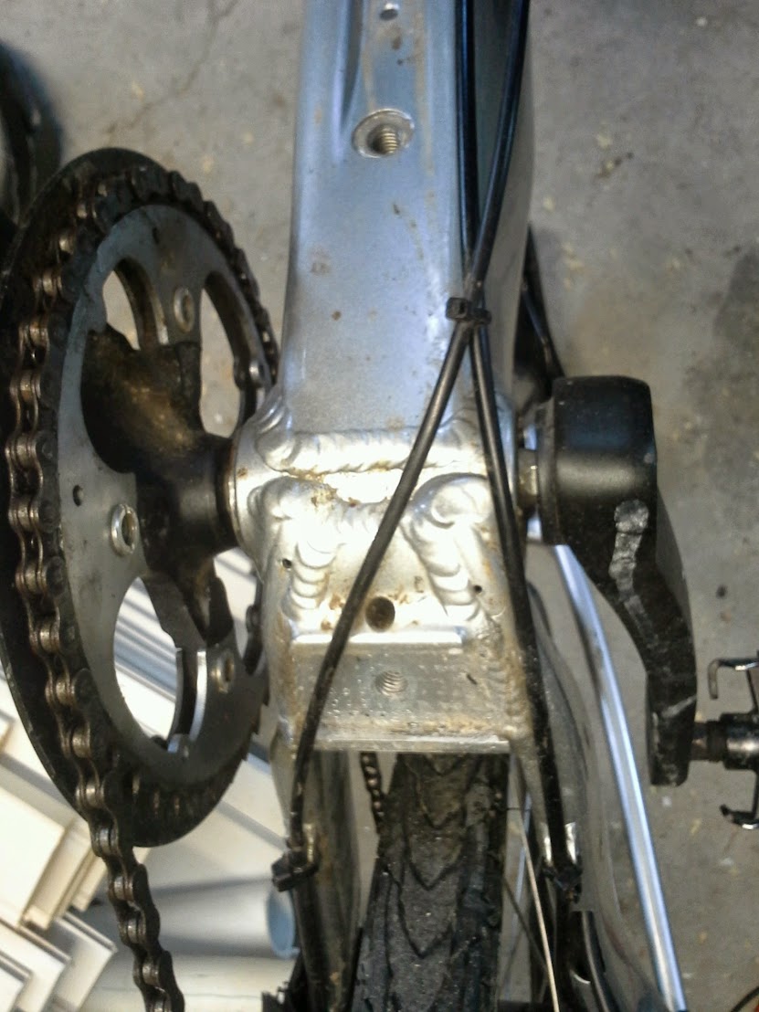
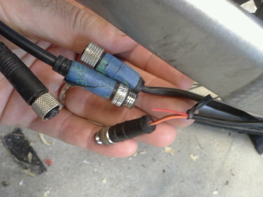
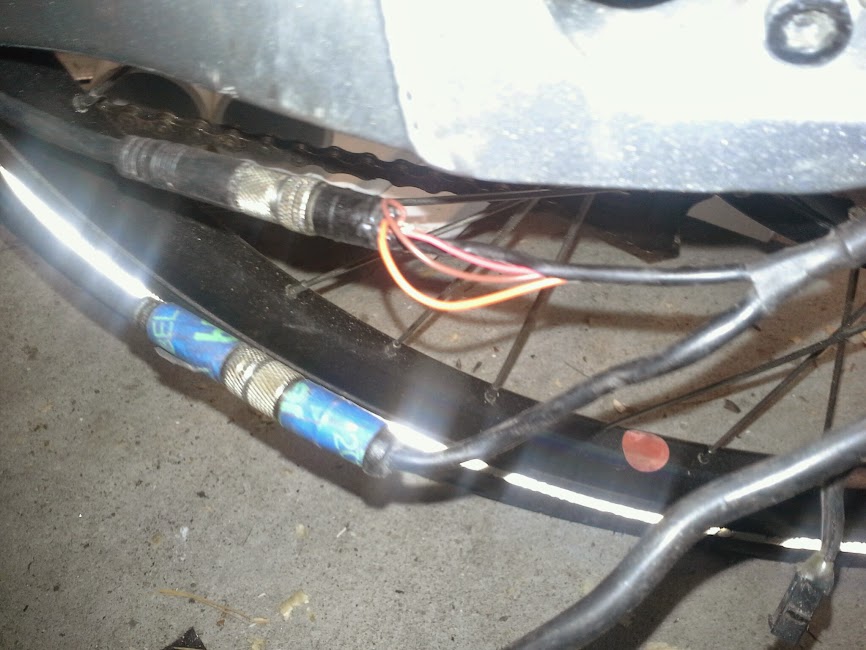
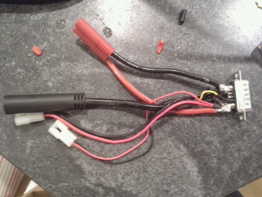
Hacking a Couple Stromers

GCinDC

100 MW
Joined
Jan 23, 2009
Messages
4,261
Location
Washington, DC
these two stromers were brought into the shop with issues, and stromer sent them replacement bikes. they sat in storage for 1.5 years and now that the local bike shop is closing down, they gave them to me (cause i happend to be chatting w/ a guy who works there and found out about them).
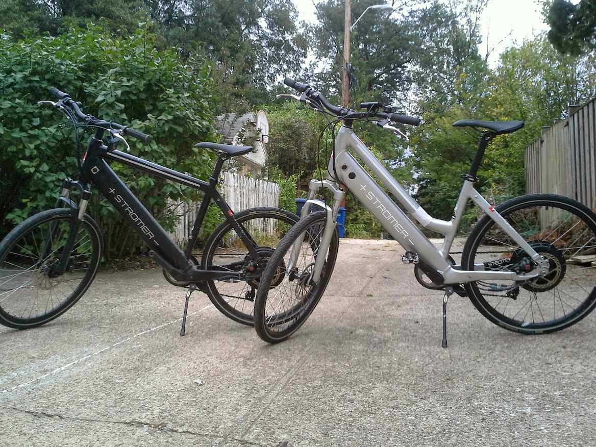
GRRARzzoikVUBYmFUc79h41yiikLjzIIKXQjJTMq3vKf=w1168-h876-no


push On button, but no response whatsoever.
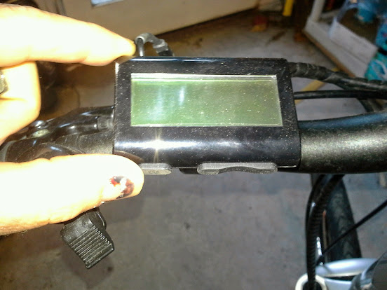
20141005_073555.jpg


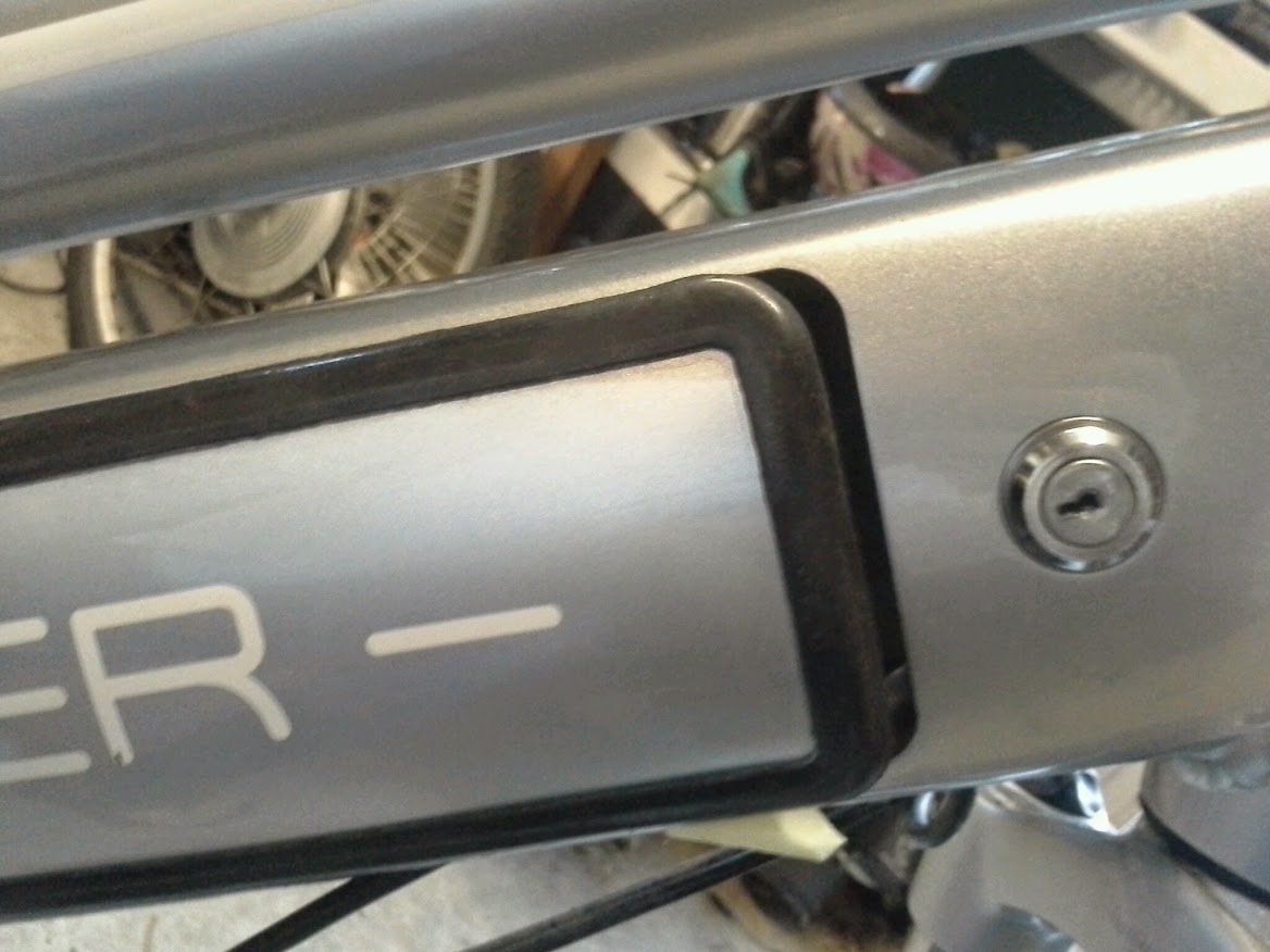
got 3 new chargers with them but no keys.

plugged in the chargers, light went red for 5 seconds then turned green.

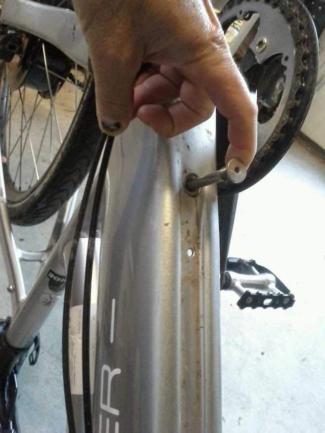
lbs tech told me i could remove this bolt and slide out the pack:
20141005_073113.jpg


20141005_073213.jpg


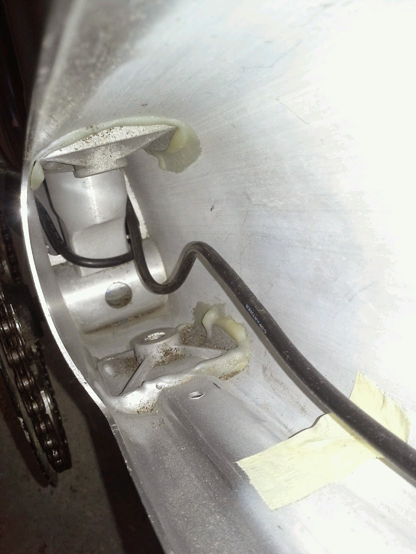
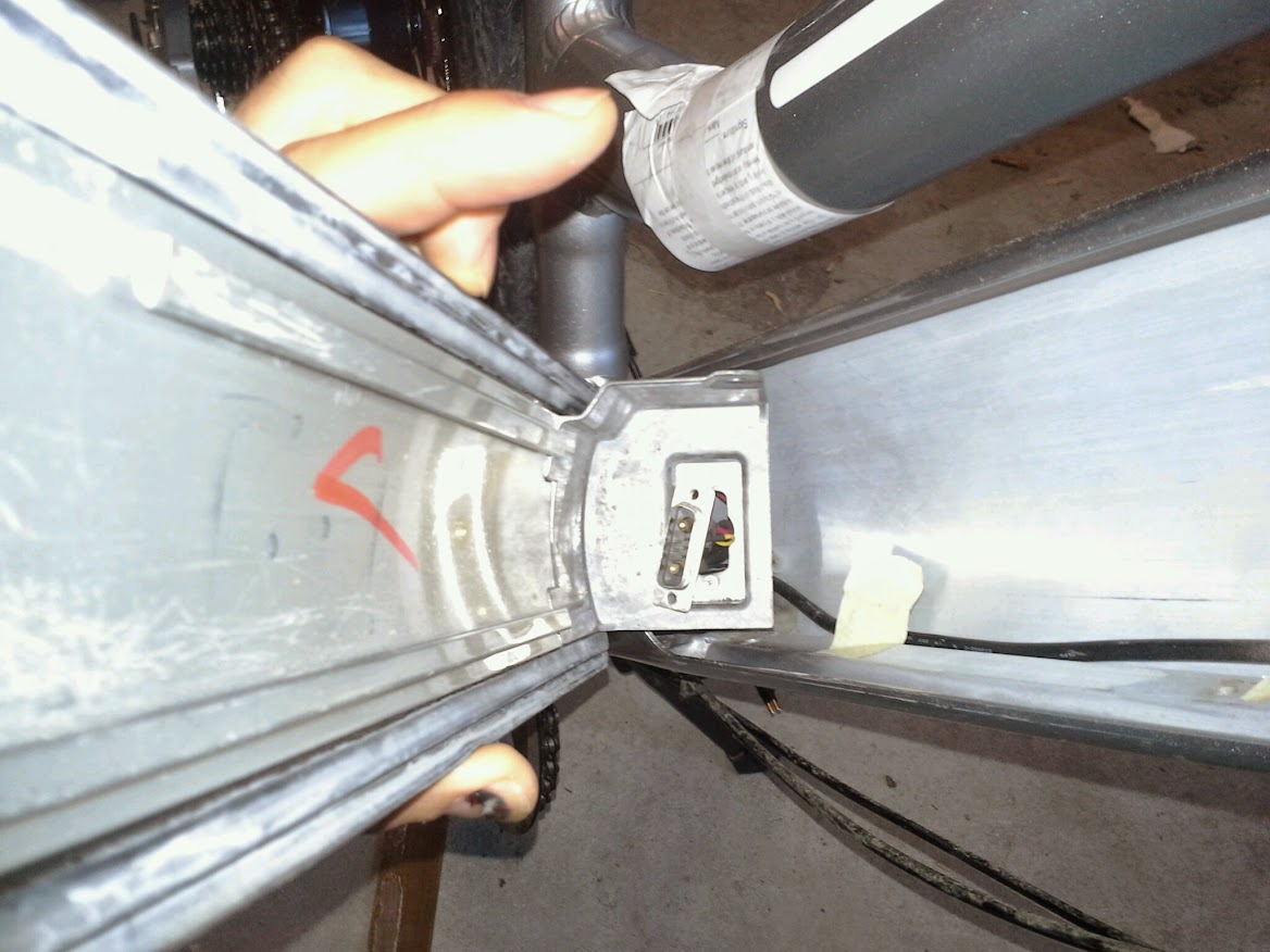
ah, well there is no battery! and here's a pic after i've started taking apart the wiring:
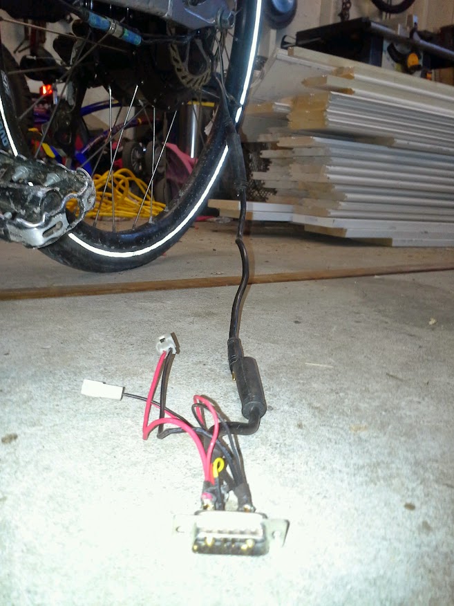
20141005_073417.jpg


20141005_073520.jpg


checked the charger voltage: 42V

peeled back some of the shrink tube and hooked it up to 41V (lipo) - no pics of this exercise - but no power to system.
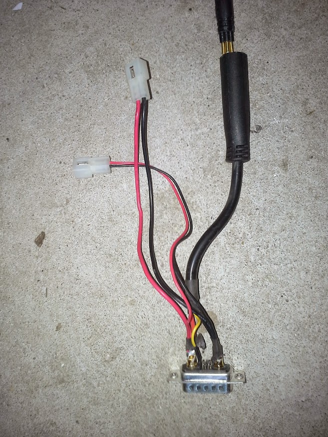
20141005_073527.jpg

perhaps i need to figure out if that yellow wire is key to operation...

hmm, but digging around online, on the stromer troubleshooting page, i see this:
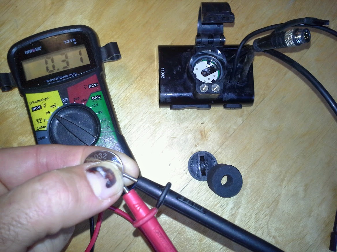
The control unit cannot be switched on. Replace the control unit’s battery. To replace, remove the unit from the handlebar. This requires a Phillips head screwdriver and a button battery (CR2032). The battery can also be replaced at your local dealer.
 
What are you planning to do - revive the stromers as is or hotrod the crap out of them?
The system looks similar to the A2B - 10s, ultramotor, half the controller inside the hub, the other half under the batt compartment. Should have four wires going to the hub.
If you pull the ultramotor apart and get rid of the controller, the motor is capable of 2-3kW easy (in my experience)
 
for my wife, just in time to replace her 5 year old 250W bionx kit that she's put 10,000 miles on.

gotta stay lightweight, number one priority.

could rewire for another controller, or could even buy replacement battery if that'll fix it. open to whatever.

no controller in batt case, must be in motor.
 
TSAR said:
system looks similar to the A2B - 10s, ultramotor, half the controller inside the hub, the other half under the batt compartment. Should have four wires going to the hub.
all the controller must be in the motor. nothing in here:
20141009_162014.jpg


even pulled off kickstand to make sure nothing under there:
20141009_161820.jpg


so i removed the battery connector from inside the compartment and hooked it up to 41V (10s2p puffy lipo).
14%2B-%2B1

but question #1: what is the yellow wire attached to (that's on one of the main connector pins? it's the only wire not hooked up the the black or red mains.

after startup i got this (MSG: NO_COM)
14%2B-%2B3


but lookee here, a broke wire!
20141009_172005.jpg


so i carved out the plastic to get at some theads, twisted them up and reconnected them:
20141009_173558.jpg


the raw alligator clips attached to the lipos were asking for trouble so i soldered in some 4mm bullets for testing purposes:
20141009_190748.jpg


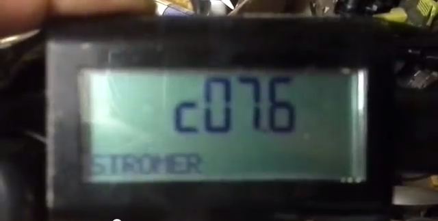
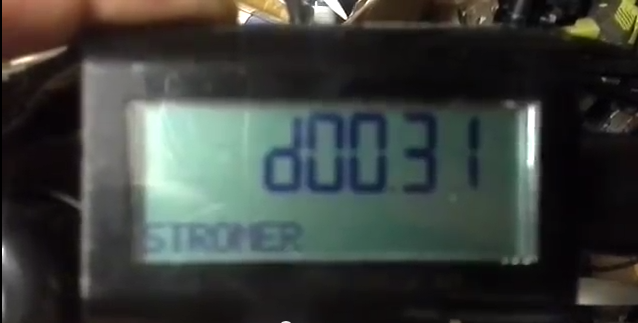
so i attached the lipos and fired it up. got two startup messages - questions 2 & 3: what do these mean?
Screen%2BShot%2B2014-10-09%2Bat%2B8.03.31%2BPM.png

Screen%2BShot%2B2014-10-09%2Bat%2B8.03.43%2BPM.png


i toggled thru the menus and saw two regen modes, one blank mode and 4 PAS modes. on braking the regen seemed to cause drag.

but the throttle or pedaling in a PAS mode did nothing. tho the bike was so light i almost thought it was helping!

so is it a clue that there's some regen happening?

need to look up those error messages...

i could redo all the wiring in case an internal connector is bad. but maybe i should try the other stromer first.

i'm guessing it's not working cause the yellow wire is not connected, and that's probably attached to the BMS somehow...

what the heck, let's check the wires coming out of the motor, if someone yanked on them as it looks like they had there could be damage:
20141009_194011.jpg


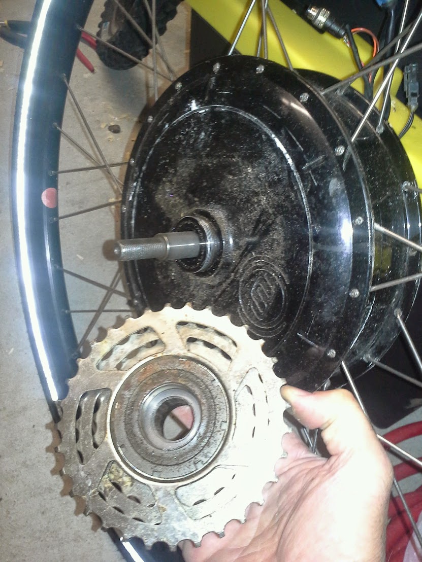
don't see any damage... so let's take a peek inside the motor. looks like it screws off. so first we remove the freewheel:
20141009_194639.jpg


now lets angle a screwdriver against one of those slots and give it a couple taps... hmm, nothing doing. maybe that sidecover doesn't screw off...
20141009_194839.jpg


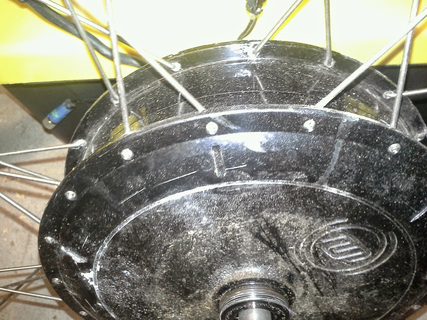
question 4: you cannot possibly tell me that motor only comes apart when the spokes are off? i can't believe that! i don't trust my eyes, and a seam could have been painted over...

so close but yet so far!

if i can get a new/used stromer batt and have some confidence the bike will run, that will be the best option for my wife. she would burn down our house in two days if she were to charge lipos. i suppose another chemistry would be fine, but if buying a batt, why not a stromer batt, esp as there is likely an electrical requirement.

i could install another hub motor/controller/batt, but this is not to be hotted up. the slower the better for her. lol.

maybe it's time to take apart and play with the other stromer and see how far i can get. lol
 
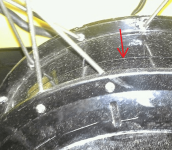
It looks like Stromer absolutely does NOT want customers taking the motor apart to play with the controller inside. The red arrow points to a seam, the shell must be made from two halves that are screwed together. It looks to me that you are right, the spokes would have to be removed first.

Stromer1.png
 
In that pic under the batt looks like it has had water/sand in it. The bikes didn't go through a flood I hope :(
 
time for a mini-cro then?
only 8kg....serious power.... :p


no.seriously now..
perhaps there might be a stromer dealer somewhere near you, that does repair and service jobs, you might be able to chat to them and find out how to open those suckers up.
 
great way to keep people out of the motor, but horrific to service. no wonder they send out replacement bikes when a wire gets broken or something!

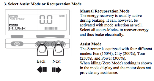
good news is i found some info online, firstly:
Screen%2BShot%2B2014-10-10%2Bat%2B6.05.21%2BAM.png

i did not see a POWER mode, and i'm wondering if that's cause it new the batt wasn't hooked up. could be an older/different version than in the guide tho..

[edit: actually it does have PAS POWER mode, so that must be the power referred here, since it's under assist mode, and the blank mode must be the idle mode. so why does it have a throttle if it's PAS only?]

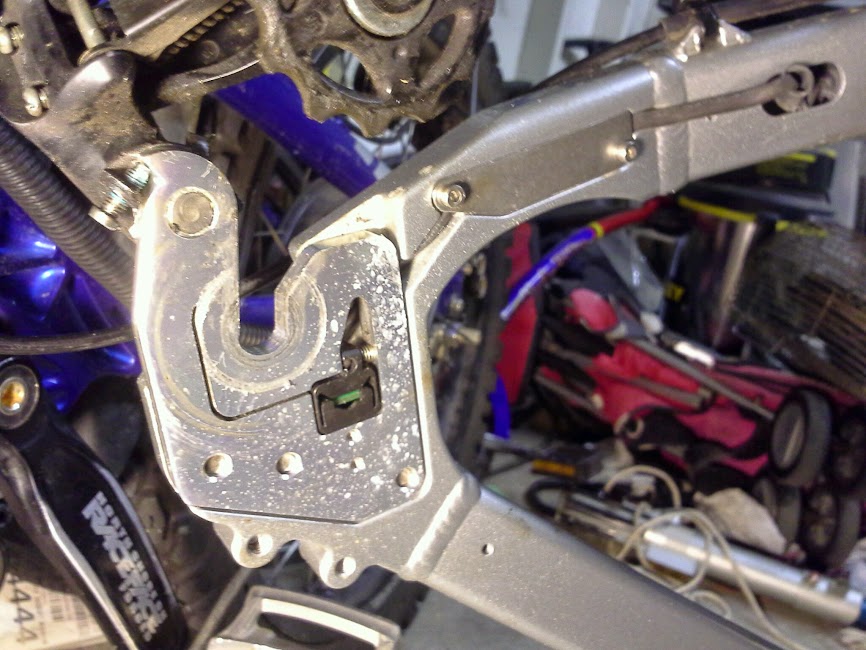
Speaking of PAS, check out this:
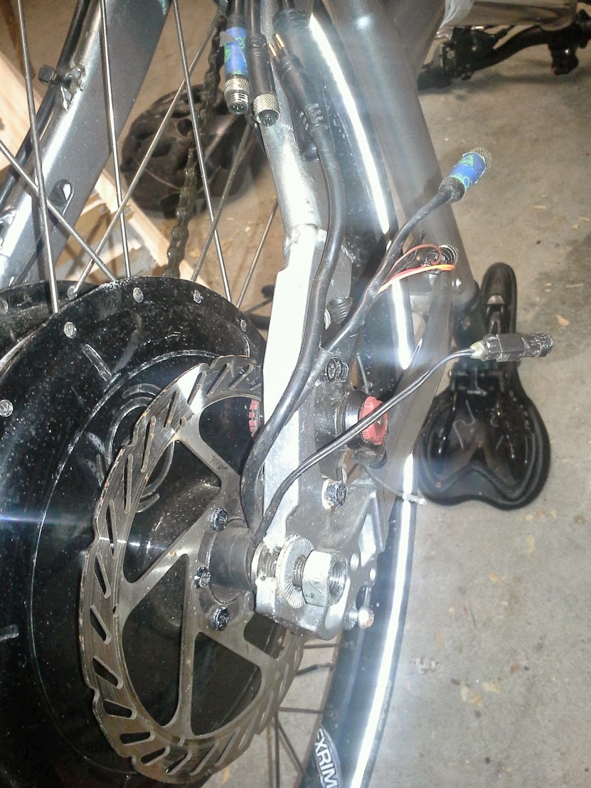
20141010_062040.jpg

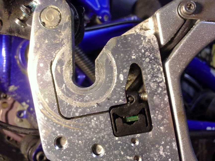
yes, that is a slice in the frame above the dropout!
20141010_061942.jpg


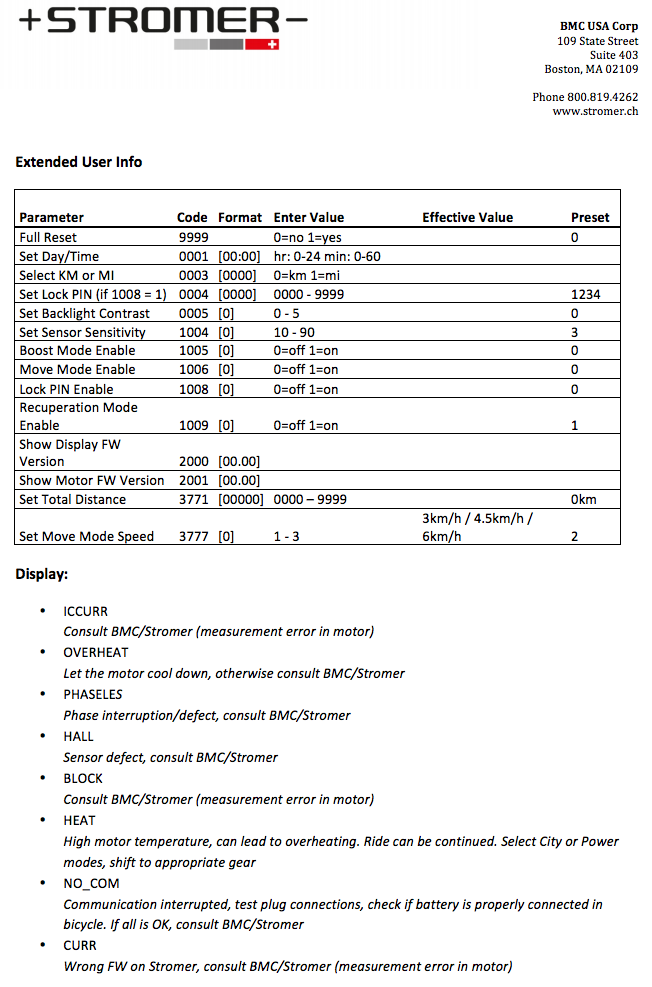
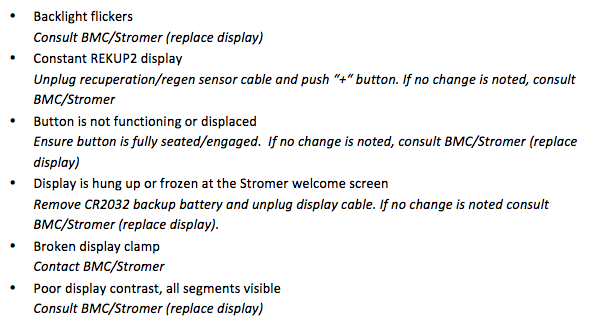
here's something else; while i did get the original NO_COM message (until i connected the broken wire) i don't see any other messages (besides the ones that flash at startup) check out the list (from here):
Screen%2BShot%2B2014-10-10%2Bat%2B6.06.29%2BAM.png

Screen%2BShot%2B2014-10-10%2Bat%2B6.06.52%2BAM.png

so the halls and phase wires are good. lol.
 
spinningmagnets said:
If one of the two motors is fried, would you be interested in selling the fried motor? You know...for science?
if fried, sure! but i'm not sure they're fried yet. there's definitely evidence of corrosion around the motor seams in places, so they've likely been ridden in salt water.

such great parts on them though! a lot to like in the design. and did see someone mention they're the same motors as the A2B, but i'm still not entirely sure what version they are. might be earlier version than ST1 actually.

i've not found good info online about how they work, so hoping others may find this thread useful down the line, when others try to fix 'em themselves..
 
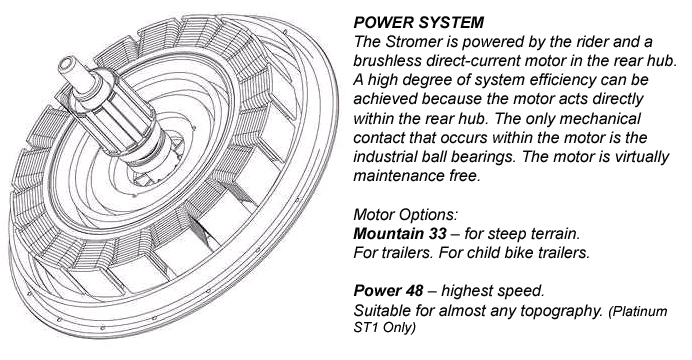
hard to find pics of an open motor. found this:
motors.jpg


but on a german forum found these:
stromermotor1.jpg

stromermotor2.jpg


since it appears to be an ultra motor, i did some searching and found this thread: Resurrecting an Ultra Motor A2B Metro with 74 volt power
edamame said:
fechter said:
Nice work!

What did you have to do to get the motor apart?

After I removed the spokes I used a 12" long 2x2 pine board and a ball peen hammer to tap one of the the halves away from the other little by little until it popped off. I did the same for the remaining case half so that I could replace bearing in that half, too. Just make sure that when you press it back together make sure to offset the spoke holes of one half against the other so they are not lined up.

another guy succeeded this way:
bklynjim said:
To get the motor out of the hub I drilled a hole in a 2x4 (you can see it in the picture above) and placed blocks between the hub and the 2x4 and simply tightened the axle bolt. It worked well. Let me know if that is not clear.
file.php
 
That is some clever? engineering. But what a service nightmare.
 
i bet the battery can be fixed also. is it sealed with the cells inside that case embedded in goop? if you can extract them and replace them then it may work with the original battery case. does look like it is the A2B motor doesn't it?
 
I've done two ultramotors so far, and yes the spokes have to be taken off at least one side of the motor to open it. The two aluminum halves are simply pressed together over a steel ring that holds the magnets. Like others said, make sure you mark the halves so that they match and alternate the spoke holes when putting back together. To pull them apart, I used 6" and 8" gear pullers on both sides, one to pull, the other to keep tension, doing one turn at a time and tapping the middle with a nylon hammer to help to even it out. It takes 10 to 15 minutes, and after the initial snap comes apart like butter. The controller is held internally by two screws from the other side. The other thread describes it in good detail, but I would add to check the motor bearings while it is open, and replace if necessary (one of mine was grinding)
 
since i've hit a dead end troubleshooting, it looks like they'll end up being nice donor bikes!

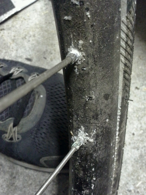
so, eeny meenie, minie moe. i'll take apart the black bike's motor first. here's the corrosion i was talking about:
20141011_182716.jpg


and man, these look worse in close up:
20141011_184328.jpg


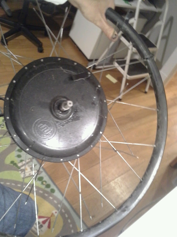
crappy pic, but i taped on the sidecover and the rim where the first two spokes go:
20141011_194027.jpg


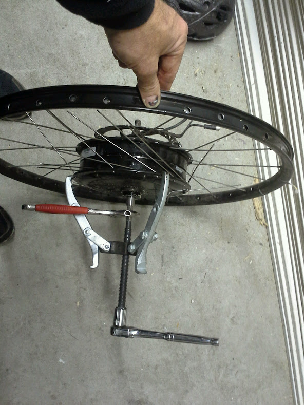
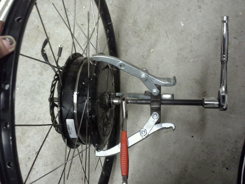
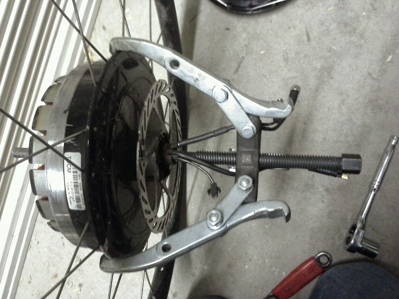
fooled around w/ a two by four, but ended up just using a gear puller:
20141011_201839.jpg


come to papa:
20141011_201932.jpg


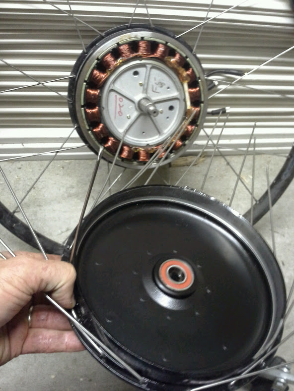
holy crap it's clean!
20141011_202006.jpg


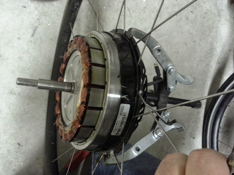
might as well pop the other side the same way:
20141011_202326.jpg

20141011_202334.jpg


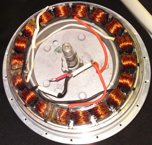
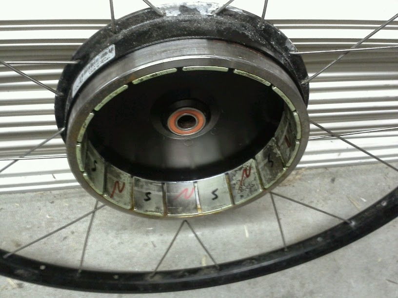
oh cute, they marked the poles:
20141011_202836.jpg


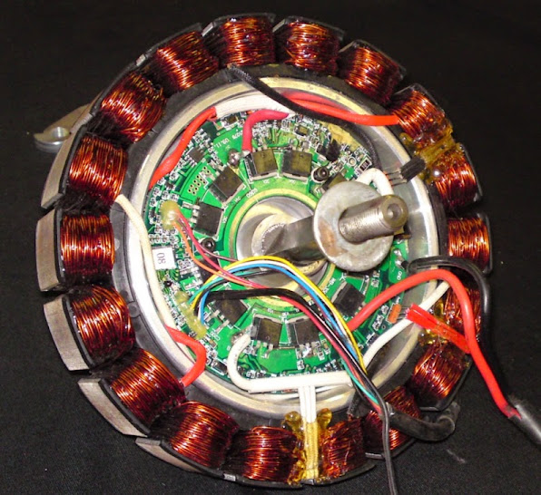
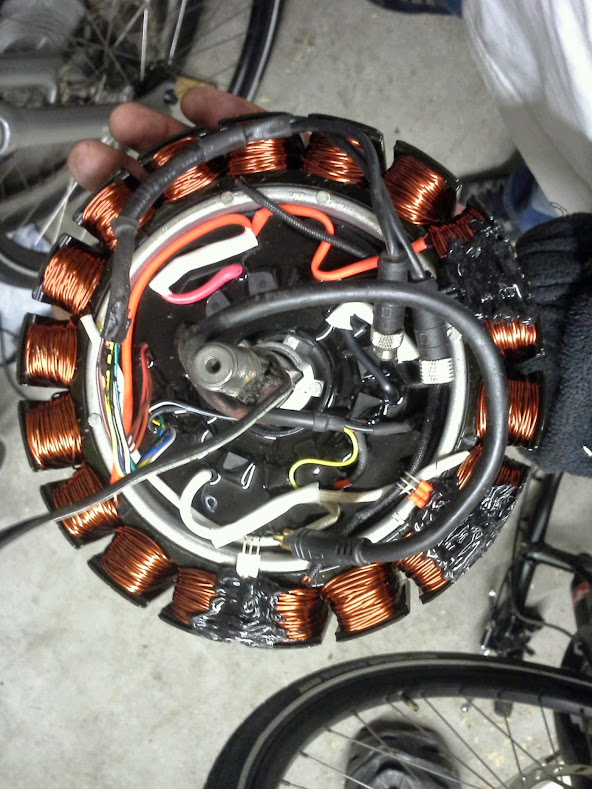
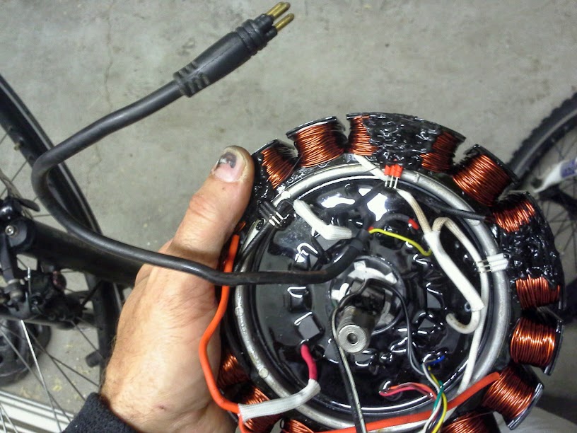
and now the controller, dipped in epoxy with fets peaking thru?
20141011_203041.jpg


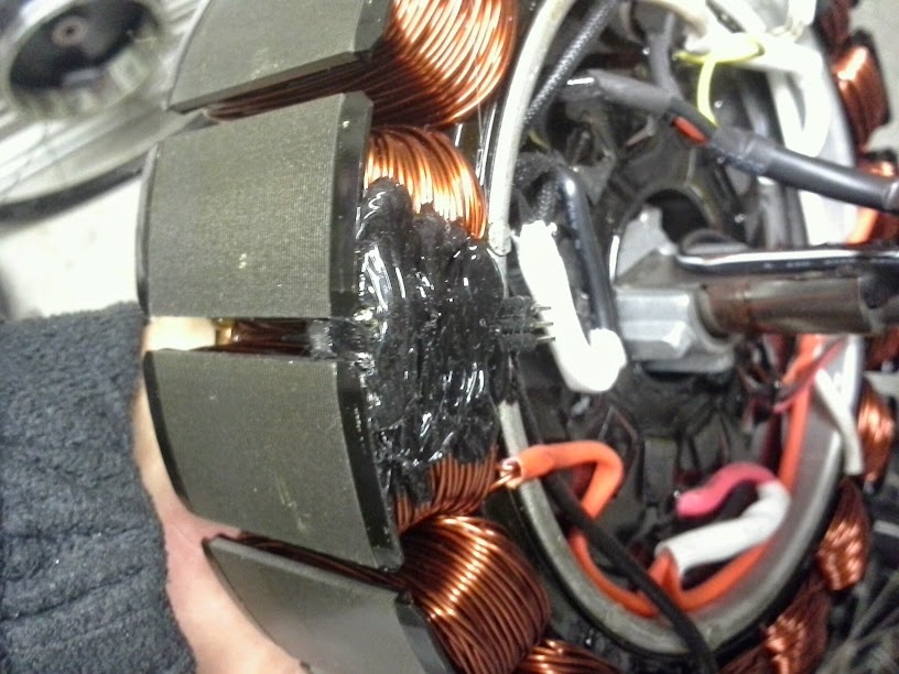
the hall sensors are near the magnets but inside the motor, the legs are exposed?
20141011_203156.jpg


and the legs go into the controller (about to become a hockey puck), so there's no way to removed the controller w/o chopping the legs?
20141011_203745.jpg


at least it has the shortest phase wires in history, since they don't even have to leave the motor.

and there's that yellow wire again. what could it be??? how about an on/off switch wire, like the little red wire that comes out of infineon motors? or is it more likely a temp sensor wire? naw, outside the motor, it maps to the battery connector, and it doesn't go up to the display that i can't tell. something that goes between BMS and controller?

anyway, that's the progress.

might make a nice adaptto stromer, maybe w/ 42V worth of long skinny lifepos?
 
That is a nice surprise that it is so clean inside. :shock: Starting with the sand in crevices in the batt comp. and the corrosion on the motor and wheels I thought sure you might find some nasties inside. Appears someone road it into the ground/no cleaning till it died.. :?
 
the controller shows no evidence of failure. non of the mosfets cooked and if you could power it up so you could find 5V on the hall sensor legs then you could put it back together enuff to rotate the wheel so the magnets can swing past the hall sensors so you could test them for functionality. then you could use those hall sensors with another controller.
 
which kit? link?

think i'm going to wait to cut wires until i call stromer tomorrow, talk troubleshooting and parts options. if dead end, gonna pop out the controller..

edit: hey dnum, the motor halls/phase wires gotta be fine, so motor can't be 'fried'. controller may be, or some part of it.
 
It would be simpler to mark it by just running a sharpie across the seam here on your first pic:
https://lh3.googleusercontent.com/-KRQ2xYaKGlg/VDnOSF0MZZI/AAAAAAAArv4/k0ZWEVrrzTo/w816-h612-no/20141011_182716.jpg

IIRC in the A2B the four wires were Pos, Neg, Throttle signal and Brake signal. Maybe the yellow wire is the e-brake/speed limiter?
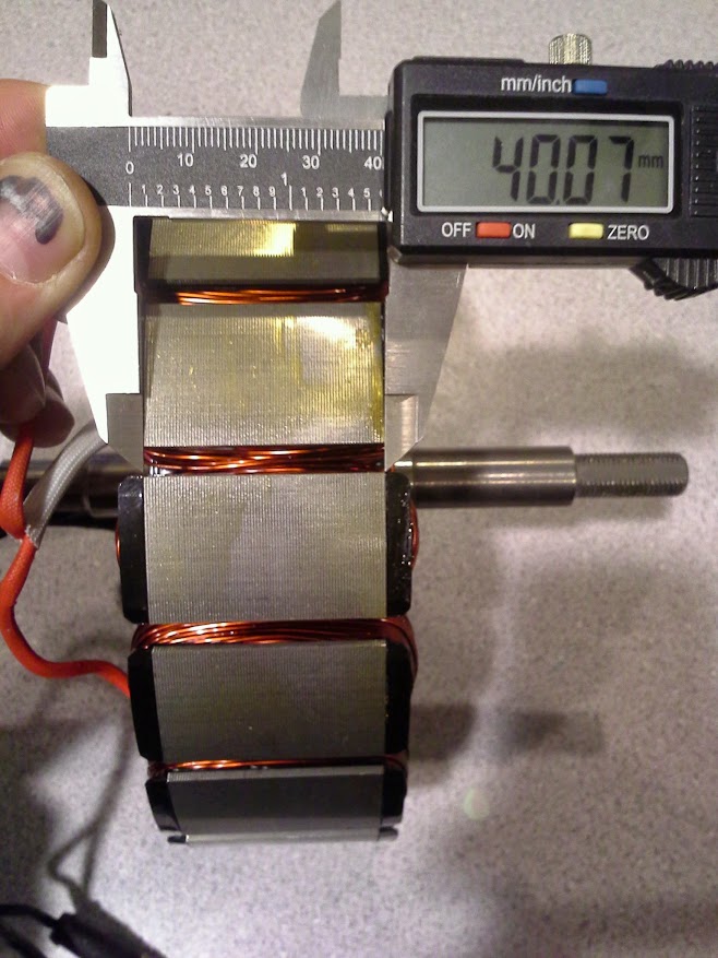
Also, the stator is 40mm wide.
 
TSAR said:
It would be simpler to mark it by just running a sharpie across the seam here on your first pic:
https://lh3.googleusercontent.com/-KRQ2xYaKGlg/VDnOSF0MZZI/AAAAAAAArv4/k0ZWEVrrzTo/w816-h612-no/20141011_182716.jpg
yep, did that too. thx.

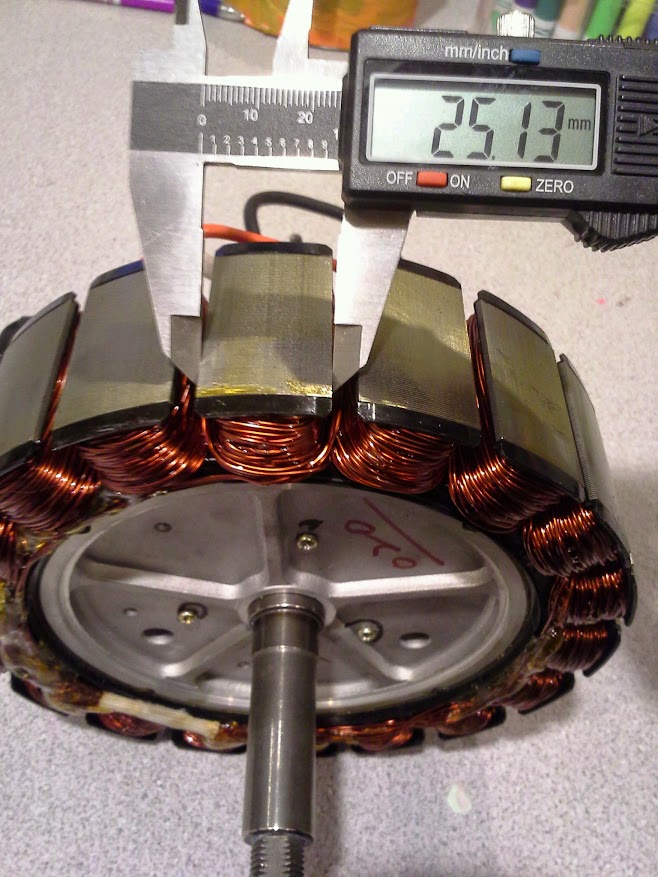
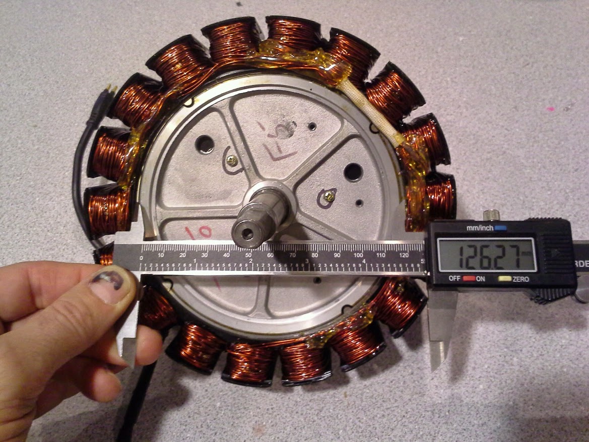
spinningmagnets said:
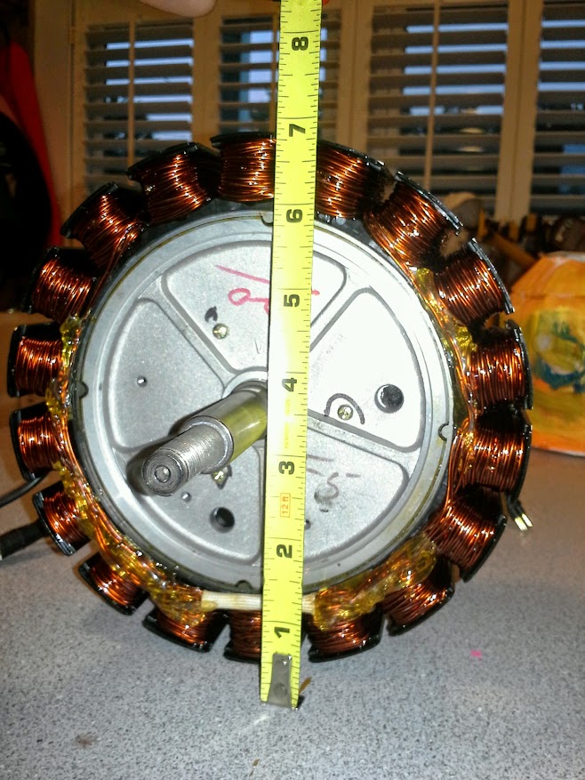
Whats the width of each stator tooth, and the OD of the stator?
these answer your q's?
20141012_182220.jpg

20141012_182313.jpg

20141012_182107.jpg

about 6-7/8"
20141012_182002.jpg

20141012_181737.jpg

this is a great motor. i'm psyched to use it w/ whichever controller. nice 8 speed freewheel, 6" disc. having all that stuff fit nicely is great.
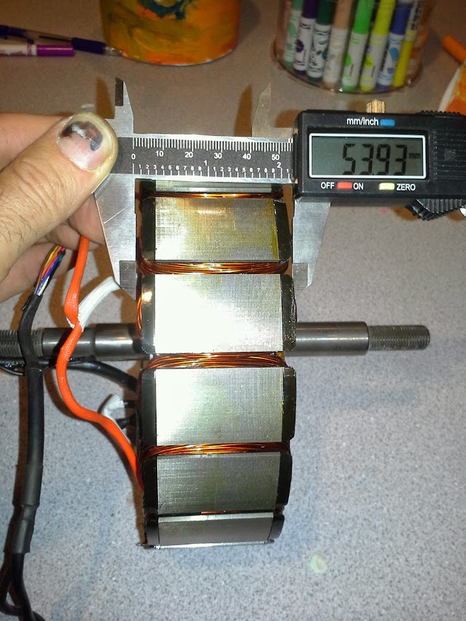
 
Well done, sir...thanks!

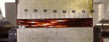
40mm /80 lams = 0.50mm each

Stator is 173mm outside diameter (6 13/16th inches, 6.625-inches)

StromerLaminations.png

I suspect the embedded controller is a very quiet sine-wave, and this unit might make a pretty great mid drive?
 
Back
Top