whatsaheadwind
1 mW
- Joined
- Jun 27, 2020
- Messages
- 14
I wrote this manual because I couldn't find any useful information on the internet that would help me diagnose a wierd problem I had on my Mid City, so I dismantled the bike, drew up a circuit diagram, and worked out how everything worked and communicated. This is the documentation of what I found.
MULTIPLE MPUs
The reason they call the PCB in the motor a controller, rather than "the computer", is because there are two microprocessor units (MPUs) in the eBike. The display is also a computer, and it does all the calculations for the odometer and speedometer, displays the PAS setting and error codes, stores the odometer record, and controls the display panel. It is in constant communication with the MPU in the controller, which is tasked with performing diagnostics on startup and with managing the motor thereafter. (If a problem develops during operation, it will cease powering the motor and communicate an error code to the display.)
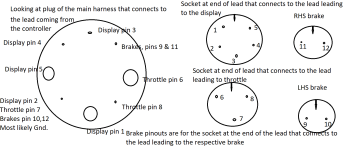
BRAKE LEVER ASSEMBLIES AND SENSORS
The brake assemblies (and sensors) are made by Tektro. The sensor is a reed switch. It bounces when a magnet passes near it, which results in a pulse or two prior to the hard-on connection. That is normal for mechanical switches activated by magnets - don't be bothered by it. The MPU in the controller will disregard the signals from the bounces and knows to only pay attention to a prolonged signal.
The sensor has to be adjusted to be in the correct position, and there may be an allen-key lock screw to lock the retainer in the correct position after the correct position is found. See https://www.youtube.com/watch?v=7Gnq2Hin9mM for the procedure Tektro use to adjust the sensor location. Their SST (special service tool) is NOT essential equipment. Their tool merely feeds low voltage through the sensor and the LED on the tool detects when current flows/ doesn't flow as you adjust the position of the sensor relative to the magnet inside the brake lever. There is supposed to be a spring behind the sensor to hold the sensor hard against the nut retainer that holds the sensor into position. That spring is very important and must be present.
Adjust the position of the sensor in the brake handle housing by disconnecting the sensor from the 4 to 1 Y harness and connecting your multimeter to the pins of the sensor, with the multimeter set to test connectivity. Tighten or loosen the "nut" retaining the sensor in the housing (which adjusts the pressure on the spring and the position of the sensor in the housing) until you're happy with how much brake handle movement is required before the multimeter indicates that the reed switch has been activated. (If you don't have a multimeter, take a torch apart and wire the sensor in series between the torch battery and the torch light.) Alternatively, just take a 7mm open-ended spanner with you and go for a test ride. You don't need the SST.
CONNECTORS
The plugs/sockets carry the name ANERMA (as seen with 10x magnifier). They are HIGO waterproof connectors. https://www.ebay.com/itm/Higo-Waterproof-Connector-2-3-4-5-6-8-pin-cable-lead-1m-ebike-electric-bafang-/302851067039.
It is possible to purchase components that appear to be identical to what you need, but which have different HIGO connectors on the cable than what you need. Be very careful that the component that you order has the correct HIGO connector on it. The colour of the connector, number of pins, and male or female are all critical.
MOTOR AND DISPLAY
The motor and display in the MidCity are DAPU products. My display is the DAPU DPLCD-P, but the button pad shown in the picture on their website is different to mine. The MD250 is the only midmotor that DAPU currently have on their website. http://www.dapumotors.com/id-26.html?t=en-us Torque sensor and motor controller are integrated within the motor body. There have been multiple generations of DAPU midmotors, seemingly all named MD250, 250 being the power rating of the motor (250W). Apparently there is or has been available an exclusive and custom build 750W version of the motor as well, used only in the US. I suspect, from info I found on the internet, that the first generation MD250 had an external controller, but current versions of the MD250 have an internal controller.
Some web pages say that DAPU is Japanese. Dapu might have been Japanese once, but their webpage http://www.dapumotors.com/Guestbook/index.html?t=en-us gives a Chinese address. One webpage I found says that DAPU is a Chinese manufacturer under Japanese management. Most reviewers on the internet praise the DAPU products highly.
The Hall sensors inside the motor are apparently not available as a separate spare part. You're expected to buy a new motor, at $1000, if the Hall sensors fail. Perhaps it is possible to desolder the faulty Hall sensor and solder in a replacement. Given the difficulty of identifying and obtaining exactly the same Hall sensor, it's probably easier to replace them all with ones of satisfactory spec.
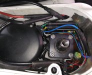
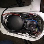
THE CONTROLLER
The controller for the Mid City is built into the LHS of the MD250 motor, and is easily replaced without having to remove the motor. You'll need a set of bits for a screwdriver that includes one that suits the screws that hold the motor cover on, a 1/2" drive hex head to remove the pedal crank, and a gear puller to remove the pedal crank from the motor. Drop a short bolt into the threaded hole before you fit the gear puller - you don't want to damage the thread. Make sure the bolt is a fall-in drop-out fit in the hole, and that the head of the bolt is just the right size to cover the pedal shaft but not the pedal crank. If you do damage the thread with the gear puller, you'll need a mid-tap to retap the thread. You can get one at any good trade tool supplier. Take the retainer bolt with you as a sample of the thread.
All the devices tested by the diagnostics are connected to the controller, therefore it makes sense to run the diagnostics on the controller MPU, not on the display MPU. This is hard to prove, but if you get an error code which you know is a furphy (ie, bogus), then I'd replace the controller, not the display.
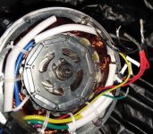
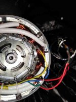
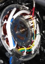
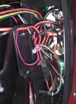
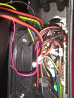
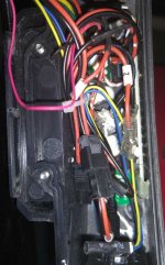
Coming from the front harness (as a single multicore) is 8 wires going straight into the controller.
Coming from the motor into the controller are 4 leads:
⦁ thick green
⦁ thick yellow
⦁ thick blue
⦁ a 4-core of blue, green, yellow, red, that comes from the hall sensors. There are usually three hall sensors in a brushless DC motor, so this would be common (VCC) plus three data.
The three heavy leads are required because the motor is brushless. Brushless motors require hall sensors to run, so the 4 core will be from the hall sensors. https://www.allaboutcircuits.com/industry-articles/3-phase-brushless-dc-motor-control-with-hall-sensors/ explains how brushless motors work.
Coming from the pedal axle housing into the controller are 2 leads:
⦁ not connected, capped, 3-core
⦁ 5-core (black, yellow, red, green, blue) going to the controller. This will be from the hall sensors that detects pedal movement. Perhaps 4 hall sensors plus VCC common? Or 3 hall sensors plus VCC plus GND? I think 4 hall sensors are more likely, because the bike is very sensitive to pedal movement.
Coming into the controller from the frame beneath the motor is:
⦁ 1 x heavy red lead providing +ve power source to the controller and motor at full battery voltage, directly from the battery
⦁ 1 x heavy black lead directly from the battery, providing GND.
⦁ 1 x 2-core from the Hall sensor on the frame adjacent to the rear wheel. As the magnet on the spoke passes the Hall sensor, a pulse is sent to the controller, which passes it on to the display MPU.
⦁ 1 x 3-core from the PCB in the front of the battery housing. This is VCC (red), GND (black), and DATA (white) providing on or off instruction to the PCB that controls the lights.
⦁ 1 x 3-core from the gear sensor (labelled gearsensor.com) beneath the motor, accessible by removing the plastic dirt cover under the motor on the frame.
CONFIGURING THE CONTROLLER
It is possible that Smartmotion have a customised version of the controller, with firmware written to their specifications, but far more likely is that they are using the standard DAPU firmware, but have configured the configurable parameters of the firmware to suit their particular specifications, in much the same way that different wheelchair manufacturers configure the parameters of the joystick controller on their wheelchairs to suit their particular requirements using software purchased from the manufacturer of the joystick. I wish I could get my hands on a copy of the software used to configure the (DAPU) controller of the Smartmotion - there's one setting that really irks me.
If one did get one's hands on the configuration software for a DAPU controller, then the means of connecting it to the Smartmotion is to unplug the Display cable from the 4 to 1 Y cable, and connect a special USB cable in place of the 4 to 1 Y cable, then plug the USB connector into a laptop and run the software. The DAPU display is a MPU itself, that communicates to the controller via 3 wire bidirectional serial comms. There are 5 wires in the multicore from the Display; one is VCC+, one is GND, and the other three are for bidirectional serial comms. Most likely SCLK (serial clock), SDIO (serial data in/ out, ie, bidirectional on one wire), and SS_n (slave select, because the chips used are designed to handle multiple slaves (Display) from one master (Controller). I haven't bothered working out which wires are VCC & GND, but that would be easy to do. I also haven't bothered measuring what VCC is, but again that would be easy to do. Probably the easiest way to identify which wire is which in the serial comms is to open up the Display and trace the connectors back to the serial IO chip, and check the pinouts of that chip on manufacturer's specifications. There are cables on the market that have been designed to perform this task for a BAFANG controller, but I have absolutely no idea whether the pinouts on a BAFANG are identical to those on a DAPU. And anyway, the cable is useless unless you also have the software.
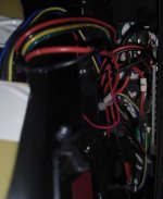
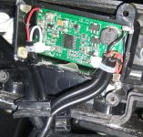
PCB IN THE FRONT OF THE BATTERY HOUSING
There is a PCB in the front of the battery housing, underneath the plastic cover. It's accessible by removing a few phillips screws. It is located there purely for convenience; it doesn't connect directly to the batery. It's function is solely to control the lights front and rear.
The PCB controlling the lights is necessary in order to deliver constant correct voltage to the lights. It also simplifies the job of the MPUs by contracting out the task of controlling the lights to a separate device, thus reducing the componentry required in the controller to control the lights and thus allowing a physically smaller controller. It may have a MPU onboard, but that is unlikely - there is no need for one to perform the tasks this PCB does.
Leading to the PCB in the front of the battery housing is:
⦁ 1 x 3 core (red, black, white) leading into the frame of the bike. This lead goes to the controller, so clearly the controller receives instruction from the display to turn on the lights and passes on the instruction to this PCB. Red and black will be power to the PCB and the lights, and white carries the data signal to the PCB to instruct it whether to turn the lights on or off.
⦁ 1 x 2 core (red, black) leading into the frame of the bike and going directly to the headlight. This lead passes over the top of the motor and is seen only by pulling out the motor.
⦁ 1 x 2 core (red, black) leading to the lights at the rear of the bike.
MAIN MULTICORE HARNESS LEADING TO CONTROLLER
The main harness coming down from the handlebars is 8 core. The main harness from the controller connects to a 4 input 1 output Y harness up near the handlebars, and is about 400mm long with no connectors between the controller and the connector outside the frame where it connects to the 4 to 1 Y cable. Those four multicore inputs to the main harness are:
⦁ 1 x 3 core from the throttle. +VCC, gnd, linear data. The throttle is a Hall sensor. The distance between the magnet and the Hall sensor is dependent upon how wide open the throttle is. Wear and tear on the throttle can affect the movement path of the magnet and thus affect the operation of the hall sensor.
⦁ 2 x 2 core from the brakes. +VCC, binary data (ie, connected or not connected).
⦁ 1 x 5 core from the Display. There'll be +VCC, GND, and three others handling bidirectional serial comms between the display MPU and the controller MPU.
This matches the 8 core harness if we assume VCC to all devices. Display has 5 wires; throttle uses VCC and GND that is also supplied to the Display, so throttle adds only 1 wire, to make 6. If the 2 x brakes are wired as OR devices, which is feasible but unlikely, then only 7 of the 8 wires in the 8 core are used. (Application of the brakes creates a connection in the reed relay in the brake sensor, so the two brake sensors could be wired in parallel, thus providing an OR logic connection for the brakes to the controller, but I'm pretty sure that the OR logic connection is done digitally at the controller and that the 2 x brakes connect separately to the controller. So we have 5 wires for the display, 1 more for the throttle, and two more for the brakes, making 8 total, which is the number of pins at the connector for the main harness.
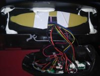
THE DISPLAY
Display has data in (from the controller) and data out (to the controller). The following list may not be complete.
DATA OUT:
⦁ PAS setting
⦁ Operation mode (normal/ torque)
⦁ Control of the lights
⦁ Perhaps some things in settings - I didn't bother checking the manual to find out.
DATA IN:
⦁ Pulse from the Hall sensor on the rear wheel, used for odometer and speedometer
⦁ Inputs from switches go direct to the display by a separate cable - there are two cables at the display: the in cable from the switches, and the cable leading to the harness that leads to the controller
⦁ Error codes. All the inputs needed for diagnostics are connected to the controller, not the display, so it makes sense to run the diagnostics on the controller and report the results to the display MPU.
The display almost certainly calculates battery voltage from it's own VCC+ve and GND, independent of the controller's assessment of voltage, and thus the display is quite capable of displaying the correct battery voltage whilst simultaneously displaying an error code 9 (high voltage), not knowing that it is displaying inconsistent data.
Processing of odometer and speed info is all done in the display MPU (microprocessor unit) from one single input: the pulses generated by the Hall sensor on the rear wheel. The distance travelled is stored in the memory of the display, not in the memory of the controller, because you can replace the controller without affecting the stored memory of distance travelled.
COMMUNICATIONS BETWEEN THE DISPLAY MPU AND THE CONTROLLER MPU
Communications between the display and the controller has to be serial and bidirectional; there aren't enough wires coming out of the display for comms to be anything else. There are five wires to the display.
⦁ VCC
⦁ Gnd
⦁ SDIO (Serial Data In Out)
⦁ SCLK (Serial clock)
⦁ SS_n (Slave Select)
The three wires unaccounted for by VCC and GND have to be bidirectional serial comms - there aren't enough wires to be anything else. Most likely they are SCLK (serial clock), SDIO (serial data in/ out, ie, bidirectional on one wire), and SS_n (slave select). The Slave Select line is probably used for handshaking. In the case of the ebike, there is only one slave: the display, but the chips used are capable of communicating between master and multiple slaves. It's half-duplex synchronous communications, bidirectional over the SDIO line. Typically it's a fixed length packet, so that each end knows if they get the full message. Web page https://www.digikey.com/eewiki/pages/viewpage.action?pageId=27754638 proves 3 wire bidirectional comms components exist; whether this is precisely how the job is done on the Smartmotion is unknown, but it has to be 3 wire bidirectional comms between the display and the controller on the DAPU system because there aren't enough wires for it to be anything else.
MULTIPLE MPUs
The reason they call the PCB in the motor a controller, rather than "the computer", is because there are two microprocessor units (MPUs) in the eBike. The display is also a computer, and it does all the calculations for the odometer and speedometer, displays the PAS setting and error codes, stores the odometer record, and controls the display panel. It is in constant communication with the MPU in the controller, which is tasked with performing diagnostics on startup and with managing the motor thereafter. (If a problem develops during operation, it will cease powering the motor and communicate an error code to the display.)
BRAKE LEVER ASSEMBLIES AND SENSORS
The brake assemblies (and sensors) are made by Tektro. The sensor is a reed switch. It bounces when a magnet passes near it, which results in a pulse or two prior to the hard-on connection. That is normal for mechanical switches activated by magnets - don't be bothered by it. The MPU in the controller will disregard the signals from the bounces and knows to only pay attention to a prolonged signal.
The sensor has to be adjusted to be in the correct position, and there may be an allen-key lock screw to lock the retainer in the correct position after the correct position is found. See https://www.youtube.com/watch?v=7Gnq2Hin9mM for the procedure Tektro use to adjust the sensor location. Their SST (special service tool) is NOT essential equipment. Their tool merely feeds low voltage through the sensor and the LED on the tool detects when current flows/ doesn't flow as you adjust the position of the sensor relative to the magnet inside the brake lever. There is supposed to be a spring behind the sensor to hold the sensor hard against the nut retainer that holds the sensor into position. That spring is very important and must be present.
Adjust the position of the sensor in the brake handle housing by disconnecting the sensor from the 4 to 1 Y harness and connecting your multimeter to the pins of the sensor, with the multimeter set to test connectivity. Tighten or loosen the "nut" retaining the sensor in the housing (which adjusts the pressure on the spring and the position of the sensor in the housing) until you're happy with how much brake handle movement is required before the multimeter indicates that the reed switch has been activated. (If you don't have a multimeter, take a torch apart and wire the sensor in series between the torch battery and the torch light.) Alternatively, just take a 7mm open-ended spanner with you and go for a test ride. You don't need the SST.
CONNECTORS
The plugs/sockets carry the name ANERMA (as seen with 10x magnifier). They are HIGO waterproof connectors. https://www.ebay.com/itm/Higo-Waterproof-Connector-2-3-4-5-6-8-pin-cable-lead-1m-ebike-electric-bafang-/302851067039.
It is possible to purchase components that appear to be identical to what you need, but which have different HIGO connectors on the cable than what you need. Be very careful that the component that you order has the correct HIGO connector on it. The colour of the connector, number of pins, and male or female are all critical.
MOTOR AND DISPLAY
The motor and display in the MidCity are DAPU products. My display is the DAPU DPLCD-P, but the button pad shown in the picture on their website is different to mine. The MD250 is the only midmotor that DAPU currently have on their website. http://www.dapumotors.com/id-26.html?t=en-us Torque sensor and motor controller are integrated within the motor body. There have been multiple generations of DAPU midmotors, seemingly all named MD250, 250 being the power rating of the motor (250W). Apparently there is or has been available an exclusive and custom build 750W version of the motor as well, used only in the US. I suspect, from info I found on the internet, that the first generation MD250 had an external controller, but current versions of the MD250 have an internal controller.
Some web pages say that DAPU is Japanese. Dapu might have been Japanese once, but their webpage http://www.dapumotors.com/Guestbook/index.html?t=en-us gives a Chinese address. One webpage I found says that DAPU is a Chinese manufacturer under Japanese management. Most reviewers on the internet praise the DAPU products highly.
The Hall sensors inside the motor are apparently not available as a separate spare part. You're expected to buy a new motor, at $1000, if the Hall sensors fail. Perhaps it is possible to desolder the faulty Hall sensor and solder in a replacement. Given the difficulty of identifying and obtaining exactly the same Hall sensor, it's probably easier to replace them all with ones of satisfactory spec.
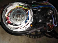
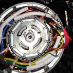
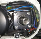
THE CONTROLLER
The controller for the Mid City is built into the LHS of the MD250 motor, and is easily replaced without having to remove the motor. You'll need a set of bits for a screwdriver that includes one that suits the screws that hold the motor cover on, a 1/2" drive hex head to remove the pedal crank, and a gear puller to remove the pedal crank from the motor. Drop a short bolt into the threaded hole before you fit the gear puller - you don't want to damage the thread. Make sure the bolt is a fall-in drop-out fit in the hole, and that the head of the bolt is just the right size to cover the pedal shaft but not the pedal crank. If you do damage the thread with the gear puller, you'll need a mid-tap to retap the thread. You can get one at any good trade tool supplier. Take the retainer bolt with you as a sample of the thread.
All the devices tested by the diagnostics are connected to the controller, therefore it makes sense to run the diagnostics on the controller MPU, not on the display MPU. This is hard to prove, but if you get an error code which you know is a furphy (ie, bogus), then I'd replace the controller, not the display.
Coming from the front harness (as a single multicore) is 8 wires going straight into the controller.
Coming from the motor into the controller are 4 leads:
⦁ thick green
⦁ thick yellow
⦁ thick blue
⦁ a 4-core of blue, green, yellow, red, that comes from the hall sensors. There are usually three hall sensors in a brushless DC motor, so this would be common (VCC) plus three data.
The three heavy leads are required because the motor is brushless. Brushless motors require hall sensors to run, so the 4 core will be from the hall sensors. https://www.allaboutcircuits.com/industry-articles/3-phase-brushless-dc-motor-control-with-hall-sensors/ explains how brushless motors work.
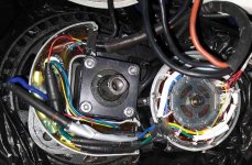
Coming from the pedal axle housing into the controller are 2 leads:
⦁ not connected, capped, 3-core
⦁ 5-core (black, yellow, red, green, blue) going to the controller. This will be from the hall sensors that detects pedal movement. Perhaps 4 hall sensors plus VCC common? Or 3 hall sensors plus VCC plus GND? I think 4 hall sensors are more likely, because the bike is very sensitive to pedal movement.
Coming into the controller from the frame beneath the motor is:
⦁ 1 x heavy red lead providing +ve power source to the controller and motor at full battery voltage, directly from the battery
⦁ 1 x heavy black lead directly from the battery, providing GND.
⦁ 1 x 2-core from the Hall sensor on the frame adjacent to the rear wheel. As the magnet on the spoke passes the Hall sensor, a pulse is sent to the controller, which passes it on to the display MPU.
⦁ 1 x 3-core from the PCB in the front of the battery housing. This is VCC (red), GND (black), and DATA (white) providing on or off instruction to the PCB that controls the lights.
⦁ 1 x 3-core from the gear sensor (labelled gearsensor.com) beneath the motor, accessible by removing the plastic dirt cover under the motor on the frame.
CONFIGURING THE CONTROLLER
It is possible that Smartmotion have a customised version of the controller, with firmware written to their specifications, but far more likely is that they are using the standard DAPU firmware, but have configured the configurable parameters of the firmware to suit their particular specifications, in much the same way that different wheelchair manufacturers configure the parameters of the joystick controller on their wheelchairs to suit their particular requirements using software purchased from the manufacturer of the joystick. I wish I could get my hands on a copy of the software used to configure the (DAPU) controller of the Smartmotion - there's one setting that really irks me.
If one did get one's hands on the configuration software for a DAPU controller, then the means of connecting it to the Smartmotion is to unplug the Display cable from the 4 to 1 Y cable, and connect a special USB cable in place of the 4 to 1 Y cable, then plug the USB connector into a laptop and run the software. The DAPU display is a MPU itself, that communicates to the controller via 3 wire bidirectional serial comms. There are 5 wires in the multicore from the Display; one is VCC+, one is GND, and the other three are for bidirectional serial comms. Most likely SCLK (serial clock), SDIO (serial data in/ out, ie, bidirectional on one wire), and SS_n (slave select, because the chips used are designed to handle multiple slaves (Display) from one master (Controller). I haven't bothered working out which wires are VCC & GND, but that would be easy to do. I also haven't bothered measuring what VCC is, but again that would be easy to do. Probably the easiest way to identify which wire is which in the serial comms is to open up the Display and trace the connectors back to the serial IO chip, and check the pinouts of that chip on manufacturer's specifications. There are cables on the market that have been designed to perform this task for a BAFANG controller, but I have absolutely no idea whether the pinouts on a BAFANG are identical to those on a DAPU. And anyway, the cable is useless unless you also have the software.
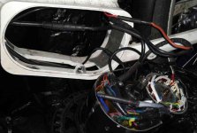
PCB IN THE FRONT OF THE BATTERY HOUSING
There is a PCB in the front of the battery housing, underneath the plastic cover. It's accessible by removing a few phillips screws. It is located there purely for convenience; it doesn't connect directly to the batery. It's function is solely to control the lights front and rear.
The PCB controlling the lights is necessary in order to deliver constant correct voltage to the lights. It also simplifies the job of the MPUs by contracting out the task of controlling the lights to a separate device, thus reducing the componentry required in the controller to control the lights and thus allowing a physically smaller controller. It may have a MPU onboard, but that is unlikely - there is no need for one to perform the tasks this PCB does.
Leading to the PCB in the front of the battery housing is:
⦁ 1 x 3 core (red, black, white) leading into the frame of the bike. This lead goes to the controller, so clearly the controller receives instruction from the display to turn on the lights and passes on the instruction to this PCB. Red and black will be power to the PCB and the lights, and white carries the data signal to the PCB to instruct it whether to turn the lights on or off.
⦁ 1 x 2 core (red, black) leading into the frame of the bike and going directly to the headlight. This lead passes over the top of the motor and is seen only by pulling out the motor.
⦁ 1 x 2 core (red, black) leading to the lights at the rear of the bike.
MAIN MULTICORE HARNESS LEADING TO CONTROLLER
The main harness coming down from the handlebars is 8 core. The main harness from the controller connects to a 4 input 1 output Y harness up near the handlebars, and is about 400mm long with no connectors between the controller and the connector outside the frame where it connects to the 4 to 1 Y cable. Those four multicore inputs to the main harness are:
⦁ 1 x 3 core from the throttle. +VCC, gnd, linear data. The throttle is a Hall sensor. The distance between the magnet and the Hall sensor is dependent upon how wide open the throttle is. Wear and tear on the throttle can affect the movement path of the magnet and thus affect the operation of the hall sensor.
⦁ 2 x 2 core from the brakes. +VCC, binary data (ie, connected or not connected).
⦁ 1 x 5 core from the Display. There'll be +VCC, GND, and three others handling bidirectional serial comms between the display MPU and the controller MPU.
This matches the 8 core harness if we assume VCC to all devices. Display has 5 wires; throttle uses VCC and GND that is also supplied to the Display, so throttle adds only 1 wire, to make 6. If the 2 x brakes are wired as OR devices, which is feasible but unlikely, then only 7 of the 8 wires in the 8 core are used. (Application of the brakes creates a connection in the reed relay in the brake sensor, so the two brake sensors could be wired in parallel, thus providing an OR logic connection for the brakes to the controller, but I'm pretty sure that the OR logic connection is done digitally at the controller and that the 2 x brakes connect separately to the controller. So we have 5 wires for the display, 1 more for the throttle, and two more for the brakes, making 8 total, which is the number of pins at the connector for the main harness.
THE DISPLAY
Display has data in (from the controller) and data out (to the controller). The following list may not be complete.
DATA OUT:
⦁ PAS setting
⦁ Operation mode (normal/ torque)
⦁ Control of the lights
⦁ Perhaps some things in settings - I didn't bother checking the manual to find out.
DATA IN:
⦁ Pulse from the Hall sensor on the rear wheel, used for odometer and speedometer
⦁ Inputs from switches go direct to the display by a separate cable - there are two cables at the display: the in cable from the switches, and the cable leading to the harness that leads to the controller
⦁ Error codes. All the inputs needed for diagnostics are connected to the controller, not the display, so it makes sense to run the diagnostics on the controller and report the results to the display MPU.
The display almost certainly calculates battery voltage from it's own VCC+ve and GND, independent of the controller's assessment of voltage, and thus the display is quite capable of displaying the correct battery voltage whilst simultaneously displaying an error code 9 (high voltage), not knowing that it is displaying inconsistent data.
Processing of odometer and speed info is all done in the display MPU (microprocessor unit) from one single input: the pulses generated by the Hall sensor on the rear wheel. The distance travelled is stored in the memory of the display, not in the memory of the controller, because you can replace the controller without affecting the stored memory of distance travelled.
COMMUNICATIONS BETWEEN THE DISPLAY MPU AND THE CONTROLLER MPU
Communications between the display and the controller has to be serial and bidirectional; there aren't enough wires coming out of the display for comms to be anything else. There are five wires to the display.
⦁ VCC
⦁ Gnd
⦁ SDIO (Serial Data In Out)
⦁ SCLK (Serial clock)
⦁ SS_n (Slave Select)
The three wires unaccounted for by VCC and GND have to be bidirectional serial comms - there aren't enough wires to be anything else. Most likely they are SCLK (serial clock), SDIO (serial data in/ out, ie, bidirectional on one wire), and SS_n (slave select). The Slave Select line is probably used for handshaking. In the case of the ebike, there is only one slave: the display, but the chips used are capable of communicating between master and multiple slaves. It's half-duplex synchronous communications, bidirectional over the SDIO line. Typically it's a fixed length packet, so that each end knows if they get the full message. Web page https://www.digikey.com/eewiki/pages/viewpage.action?pageId=27754638 proves 3 wire bidirectional comms components exist; whether this is precisely how the job is done on the Smartmotion is unknown, but it has to be 3 wire bidirectional comms between the display and the controller on the DAPU system because there aren't enough wires for it to be anything else.
Attachments
-
Smartmotion MidCity manual 67.rtf18.9 KB · Views: 218
-
Smartmotion MidCity schematic.pdf284.9 KB · Views: 154
-
 MD250 Controller.jpg138.2 KB · Views: 3,405
 -
 MD250 wiring from above.jpg139.4 KB · Views: 3,409
 -
 MD250 wiring in frame.jpg108.3 KB · Views: 3,406
 -
 PCB controlling lights.jpg218.6 KB · Views: 3,409
")