Throttle Smoother 3.0 - Linear Ramp Circuit

fechter

Administrator
Staff member
Joined
Dec 31, 2006
Messages
16,548
Location
California Bay Area, USA
Here's something I've been brewing for a long time. This is still in the development stage. In other words, I have not actually built one yet so there could be some tweaking necessary.

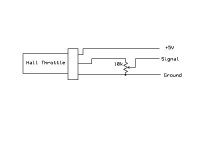
The crudest version of the 'throttle smoother' is simply a pot in series with the ground wire of the throttle that allows you to adjust the zero point of the throttle. This typically gives a better response at the low end and reduces the tendency to have a surge of power on takeoff.

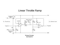
This circuit has that feature, as well as corresponding high side pot to adjust the maximum throttle. This will allow the throttle to work throughout it's entire range of motion. These adjustment pots can be left off if only the ramp control is desired.

The main feature is a true linear ramp circuit that is adjustable for ramp speed. If the throttle is suddenly increased, the output ramps up linearly at a fixed rate until the output matches the throttle setting. If the throttle is suddenly decreased, the output decreases at the rate of the input. The ramp speed adjustment can be varied from near zero to about 5 seconds for full swing. The value of VR1 and C1 determine the ramp rate.

Most ramp circuits delay the decrease in throttle at the same rate as the increase. This is bad when you want to do a panic stop. The diodes provide a separate rate in each direction. If you wanted some delay in the decrease, adding a resistor in series with D2 would allow this.

The circuit will output a signal that matches the input. This should work over the entire 0-5v range if the specified op amp is used. Most hall effect throttles don't go all the way to the rails, so pretty much any op amp should work for this. For controllers that need a full 0-5v range, a rail-to-rail op amp is needed. For a typical hall effect setup, a cheap op amp like a TL082 should work fine.

Timing capacitor C1 need to be non polar. A MLCC or non polar electrolytic should be used. You can place two regular electrolytics back to back to make a non polar if the part is hard to find. Just remember the capacitance of two series caps is half the value of the individual ones.
Linear Throttle Ramp 1.jpg

Soooo... what's so great about this? By using a linear ramp, the current draw of the motor during acceleration will be nearly constant. This reduces current peaks that cause component strain and wasted power. Motor and controller heating will be reduced as well. If the ramp speed is too fast, it will behave like it did without the circuit. If the ramp speed is too slow, it could be annoying. It should be possible to set the ramp speed such that the overall acceleration is not reduced significantly, but you still shave some excess watts during takeoff. For maximizing range, a slower ramp time is better.

For very high powered setups, like Luke's DeathBike, a slower ramp will help keep the front wheel on the ground, even when ridden by an idiot.
 
if i just wanted to reduce the speed to a legal 32kph, where would i install a pot and what value? (not asking for a specific resistance, obviously there would be fine-tuning)
 
ian.mich said:
if i just wanted to reduce the speed to a legal 32kph, where would i install a pot and what value? (not asking for a specific resistance, obviously there would be fine-tuning)

A single pot set up as a voltage divider would limit the maximum throttle. While this would work, it won't allow you to get full power for hill climbing. Something that actually measures the speed would be better, but way more complex.

Here's what the divider looks like. The pot could be about anything from 5K to 20K. A 10 turn pot makes the adjustment more precise. You could also have a switch to bypass the limiter (hidden switch?) for 'off road' use.Throttle limiter2.jpg
 
Pretty cool! I came up with something very similar a while back. Got to love that 'validation feeling' when someone else dreams up a similar idea!

http://endless-sphere.com/forums/viewtopic.php?f=2&t=33963&hilit=throttle&start=15#p494371

But never built it...really didn't need it for my current bikes.
 
Who around here has a high-powered bike with a jumpy throttle? Fechter, if I pay for the parts, will you solder one of these gizmos up and send it to "an E-bike to be determined" so it can be harshly tested?

I have had a fondness for Internally-Geared-Hubs (IGH), especially as a method for giving a non-hub motor at least 3 gears to work with. But shock-loads can snap the teeth, and several builders have verified if they overload their non-hub drivetrain, an external chain will skip, but not break (even if they break, an external gear cluster and chain are easy and cheap to replace).

I have heard that adjusting the phase-amp ratio helps, it can cut power at lower RPMs and still allow full power at the top. Which controllers allow adjusting phase-amps, and what are the methods for doing that?

The several cups of coffee I just drank are making me impatient, and I demand answers, dammit!
 
GMUseless said:
Pretty cool! I came up with something very similar a while back. Got to love that 'validation feeling' when someone else dreams up a similar idea!

http://endless-sphere.com/forums/viewtopic.php?f=2&t=33963&hilit=throttle&start=15#p494371

But never built it...really didn't need it for my current bikes.

Ah, that looks much like an earlier version of mine. That approach would work too, but not a linear ramp.

spinningmagnets said:
The several cups of coffee I just drank are making me impatient, and I demand answers, dammit!

I'll try to make a layout of it. I'd also like to at least make it on a breadboard to verify it works as expected (my version of ghetto spice). If I can verify the design, I'll see about hacking up a prototype on a perf board. It might be a little ugly but should work fine. I'll try to estimate the cost of parts.

By using a linear ramp, the loading on the drive train will be nearly constant during flat ground acceleration and be a function of vehicle weight. This can greatly reduce peak forces on the drive parts while still offering full power. A limiter based on motor current would be the best approach, but it is much more complex and difficult to get dialed in. This will have nearly the same effect but much simpler to make.
 
OK, finally got around to breadboard testing. Ghetto SPICE rocks.
The circuit works largely as expected. Ramp was very linear and adjustable. Downward input responded immediately (or at least fast enough). The RC values were a bit off, and I could get it to take almost 20 seconds to go the full range at maximum. I think about half that would be better. The output voltage settles exactly on the input voltage give or take a few millivolts.

One odd thing; If I held the input within a narrow range around 4.3v, I could get a slight oscillation in the output. This could cause a really annoying throttle surge in practice. 4.3v is above the normal maximum range for most controllers, so probably wouldn't be an issue anyway, but I want to find out exactly why it does that.

I also figured out D1 in the original schematic is unnecessary and improves things if left out. Fewer parts = better.
The connection between the range pots VR2 and VR3 should be removed to minimize power consumption and tying the wiper to one side reduces the severity of a wiper going open.

Look for an updated circuit soon.
 
I managed to get in a bit more testing but need to do more. A TL082 op amp definitely won't work, as the output swing can't get below about 1.7v. I'll have to try some others I have around.

I tried several things to get rid of the oscillation, but it persists. I would like to know exactly what causes it, but I guess it's just academic, as this all happens above the maximum normal throttle signal voltage. I have a few more things to try...
It's interesting that once it starts, the amplitude slowly drops to zero and the output voltage settles on the input voltage after a few seconds.

I was originally thinking this type of asymmetrical response might be good for my old current limiter circuit. The output could drop quickly when the current limit was reached, but come back up slowly to prevent surging. After seeing the mystery oscillation in the ramp circuit, I'm having second thoughts about that. Seems like anything that adds latency, or time delay to a feedback loop causes oscillation. There has to be a good way to get rid of it, I just haven't found it yet.
 
After more scope testing it's apparent the circuit oscillates all the time, but at a frequency high enough for the integrator to filter it out exept for at the extreme high end of the range, where the frequency drops enough so it gets through the integrator. This is not really desirable, as any oscillation in the output would be bad. I may have to scrap this approach and try something else.

The other approach is to make a low current constant current source that pulls up on a capacitor, giving the upward linear ramp. Variable current makes the ramp rate variable. A diode can then pull the capacitor down quickly to provide near instant response in the downward direction. No oscillating feedback loops. This approach will take more parts, but I think not much more than the original version.

A microprocessor based version is starting to look more attractive...
 
Have you tried riding with this kind of circuit yet? I tried this approach but did everything with a micro and found it was horrible to ride with no matter where how short I set the ramp, but I was also using it on a 12kw bike with small wheels. My current setup is using variable ramp rates and is working pretty nice.
 
texaspyro said:
I see no power supply bypass caps... could cause some problems... like oscillation.

On my breadboard I have big bypass cap. I also tried sticking a MLCC directly to the chip supply pins and it did not change anything. I think the oscillation is just inherent with the hysteresis between stages. If I used a faster op amp, the frequency might stay high enough to stay filtered.

No, I haven't tried riding with it yet. I'm pretty sure it would be fine, I'm just being anally retentive about the design.
With the ramp speed fast, I'm sure it would behave just like a normal throttle. Interesting the microcontroller had trouble. Latency could be an issue with one that's too slow. Fast ones are expensive. Well, I'd never be able to write the code for it without acending a long learning curve anyway.
 
fechter said:
Interesting the microcontroller had trouble. Latency could be an issue with one that's too slow. Fast ones are expensive. Well, I'd never be able to write the code for it without acending a long learning curve anyway.

The entire loop processes in about 380uS, wasn't a speed issue. I thought everything looked great on paper and on my scope and was confident I had a winner... then I took it for a ride and realized there is no substitute for real world testing. That lesson has changed my testing routine. I am now willing to go to a real world test more quickly than previously on some designs.

I strongly encourage you to put it on your bike and give it a try. I could be completely wrong about your design as I can only speak from my own personal experience. The throttle was manageable with my ramp rate set set really fast, but was not an improvement over stock (for me).
 
zombiess said:
I strongly encourage you to put it on your bike and give it a try. I could be completely wrong about your design as I can only speak from my own personal experience. The throttle was manageable with my ramp rate set set really fast, but was not an improvement over stock (for me).

You may be completely right. Like my signature line, can't argue with real world testing.

A current mode throttle is really the best way to approch the problem. Perhaps I should work on an improved version of that instead. Previous versions were difficult to get dialed in and required some kind of additional current sensor like a shunt or hall sensor. One way around the sensor issue would be to use the one that already exists in the controller. This would require adding one or two wires to the controller board in most cases, but the spot to attach the wire is generally very easy to identify. An external shunt that can handle the maximum current would still be an option.

One version I did simply used the existing wiring between the pack and controller as a shunt. While the resistivity of copper varies a lot with temperature, in this application it wouldn't be such a big problem. In fact, it could be sort of a 'feature' as the maximum current would drop a bit if the wires got warm.

A slightly more complex circuit would allow for easier setup. The adjustments on the old circuit were interactive, so adjusting one changed the others. You could go back and forth until it was dialed in, but kind of a pain. Non-interactive adjustments would be a big improvement.

Oscillation in the control loop was also an issue in some cases. A more robust PID or PI loop filter might solve that, but PID loop tuning is a nightmare. This is where I was thinking the linear, asymmetrical ramp might help. A fast response to over current but a slow response to under current might help loop stability without allowing too much overshoot. With sufficiently low loop gain, it will tend to be pretty stable.

Here's one of the older circuits. The parts count is not much more than the linear ramp circuit.
 
Back
Top