----- All Answer about the Dewalt 36V battery and B M S ---

Doctorbass

100 GW
Joined
Apr 8, 2007
Messages
7,496
Location
Quebec, Canada East
This post is created to resume all great and true infos about the Dewalt 36V battery BMS wich ust the A123 LiFePo4 cells.

**I would keep this post clean and it would only contain info about test done with it that give real results for charging, discharging, or balancing or LVC.


Begining with:

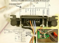
How to enable it to use with a load without bypassing it and to keep the benefit of the Low Voltage Cutout (around 25V)(24.5V at 19A and 26.5V at 7A )

Here is a video of a test i did to see how the BMS LVC react with 1.5ohms load:
<embed src="http://www.youtube.com/v/vituFUmEnU8" type="application/x-shockwave-flash" wmode="transparent" width="425" height="350"></embed>


little sumarry image i created to give many info on how to use it with
 
The next one is a summary of the connections of the Dewalt 36V Impac driver, and a circuit that enable it did by Neodymic

Doc
 

Attachments

  • Résumé des connections du BMS.JPG
    Résumé des connections du BMS.JPG
    123.2 KB · Views: 3,300
******** IMPORTANT ********** EDITED Oct 2008
(About order to disconnect the balancing wire and the power wire from the cells)
Dissassembling the pack:

1. First, Carefully unplug the BMS wires (2 group connectors of 5 wires)
it does'nt mather about the order

2. Then disconect (unsolder) the (+) positive red wire between the BMS and the (+) of the cell no 10 (pay attention to isolate it after unsoldering it!) ...... DO NOT TOUCH THE BMS CASE OR (-) WITH THE RED WIRE!)

3. Then disconect (unsolder) the (-) negative big black wire between the BMS and the (-) of the cell no 1 (pay attention to isolate it after unsoldering it!)DO NOT TOUCH THE BMS (+)WIRE WITH THE BIG BLACK WIRE!)


4. disconect (unsolder) the ground little black wire between the BMS screw and the (-) of the cell no 1 (pay attention to isolate it after unsoldering it!)

5. remove the thermistor sensor (under the yellow kapton tape)

6. that's done safely!

:wink:

Doc
 
Are you sure the connection/disconnection order has to be so exact? It would be annoying having to remember to connect things in the right order or face a destroyed BMS. Like, is it necessary to disconnect POS before NEG as long as both are done before the balancing connectors are removed?

Is there a way to stop this from being necessary?
 
No, it is absolutly necessary to disconnect the (+) and after to disconect the (-).

By this way, the (-) keep the circuit voltage reference to ground and avoid shorting in cascade the multiple fet for balancing or some IC.
(these components need to stay referenced when positive voltage is applyed on the board.(in this case.. the positive current pass thru the balancing wires.. so do not short the disconected (+) to the case.

If done in the wrong order, you will see that your BMS is blown when recinecting it to the cells. it will get hot on where the epoxy and the metal casing too. And will draw the juice from the cells thru the shorted parts.

I can assure you that if during disconnection, some wire touch others or short to the case, that will destroy it too so BE CAREFULL AND ISOLATE WITH TAPE THE DISCONNECTED WIRES FOR MAX SAFETY.

When disconnected, the red wire can EASILY touch again the (+) on the cells pack while you disconnect the (-)... so if you disconnect the (-) and the the (+) touch again the (+) of the cell, YOU BLOW IT :shock:

BE CAREFULL !
.

---this bms is very sensitive to static and any wire that touch together----

I blown 4 out of 9 !! the 5 left where done with the right methode

--I am not certain about the reverse process when reassembling the pack.--
 
I'm done with the pack assembly, but I removed the BMS from the pack. To charge, I connect the BMS; I then disconnect it before riding. So it sounds like I'd have to be careful to remember the order every time I charge or ride, lest I destroy the BMS and have to wire up a new one.

I decided to do it this way because the BMS is a little bulky, and its wires sort of force it to be at least an inch or two from the pack, wasting space.
 
Gee, the "BMS" sure is a pain in the butt.

Wonder if we can by-pass the BMS completely, with a smart charger and a Cycle Analyst meter?
 
recumbent said:
Gee, the "BMS" sure is a pain in the butt.

Wonder if we can by-pass the BMS completely, with a smart charger and a Cycle Analyst meter?

I think that would be the better way- especially for high voltage applications where the bms might blow anyways.
 
I'm pretty sure you're not entirely correct, Doctorbass, regarding connection/disconnection order. Twice I've disconnected at least some of the balancing wires before disconnecting the POS/NEG wires, yet the BMS still worked. And just now, I disconnected everything in the correct order, then reconnected everything in the correct order, yet it still somehow blew the BMS! I'm tired of this; I'd like to determine once and for all what exactly causes it to blow. When I blew it just now, it was connected to the charger but the charger had just been turned off. Does it need to be disconnected from the charger before disconnecting or reconnecting it to the batteries, even if the charger is off?
 
I've been exploring the Dewalt BMS and it's low-voltage cutoff ability.

The BMS provides access to individual cells for balancing during charging (which it does very poorly) and for low voltage discharge cutoff.

The cutoff feature seems to work reasonably well. The cutoff is NOT 25volts at the pack level. It is 2.5 volts at the cell level, which is necessary for these cells to have a long life.

Once I setup support for the resistor network to enable the cell level cutoff (http://www.neodymics.com/Images/V24ProtoSwitch070818E.pdf) I found out just how bad the charger is.

One of my new, unused packs would power a 10-amp load for only a couple minutes before the cutoff occurred. Several similar charge/discharge cycles showed the same behavior. So I took the case off the battery pack and checked the cell voltages.

Here's what cell voltages looked like after shutoff:

Code:
connector-end
           1       2       3       4       5
top      3.226   3.227   3.224   3.227   3.224
bottom   3.227   2.606   3.221   3.218   3.212
            6       7       8       9      10

Cell 7 was low and stayed low persistently over a number of charges given at least the minimum suggested 20 minutes extra time after all charger lights showed steady. Several charges were overnight.

After manually charging cell 7 to match the others the charger seemed to work properly and the pack started putting out a consistent 1.8 amphours.

When cell 7 was in it's unbalanced state I was able to observe the functioning of the BMS's low voltage cutoff. When that cell hit 2.50 volts the BMS shut off output. Overall pack voltage was around 31.5 volts!

The A123 cells are a wonderful power source. The Dewalt BMS is a poor means of taking advantage of that power source. The limited current capacity, poor balancing abilities and constricting 10-cell only sizing are simply not worth the trouble. Any one of the other A123 compatible chargers seems a much better choice.

That leaves the low voltage cutoff circuit to be cobbled together or `found' somewhere.

Many folks seem to be using these batteries `raw' -- without a cell-based low voltage cutoff. Though it may be possible to get away with this without damaging too many batteries over time -- it really seems like a poor idea that disregards the long life they're capable of if properly cared for.

There seem to be a number of possible scenarios for battery packs to get out of balance. The non-functioning balancer on the Dewalt charger and
lack of a cell-based cutoff circuit will then leave that battery vulnerable to damage. Simply leaving a battery pack on the shelf for a month or so seems to promote imbalance.


Richard
 
has anyone tried to use the "Speed Controller" built in to the Dewalt packs as a brushed motor controller?

the thought being a really simple systemusing a WE or other brushed motor, the dewalt pack and a throttle hooked up to the "Speed Control" inputs.

would it be possible?

rick
 
rkosiorek said:
has anyone tried to use the "Speed Controller" built in to the Dewalt packs as a brushed motor controller?

the thought being a really simple systemusing a WE or other brushed motor, the dewalt pack and a throttle hooked up to the "Speed Control" inputs.

would it be possible?

rick

I don't see why you couldn't do that. It might be a problem if you wanted to go with a higher voltage, but for 36v, a brushed hub motor should work just like a drill motor. I'm not sure what the current limit would be.
 
Don't the DeW bms have a 15A fuse? That might be a clue...
 
But I'm clueless...

BTW Doc, I stickified this thread since a lot of people are interested in the DeWalt packs.
 
The 15A fuse is on the negative terminal that does not go through the BMS. The negative terminal that the BMS controls is not fused, but the current limit seems to be about 20A.

-- Gary
 
Since the DeWalt drill motor is rated at 750W, the BMS should easily be able to deliver 20A, as Gary says. CycleMotorEngineer gives values for a resistor network that will enable the BMS, based on readings taken from the drill trigger potentiometer of a DeWalt drill running at full speed http://www.neodymics.com/Images/V24ProtoSwitch070818E.pdf
Doc has also managed to draw around 20A from the packs using a similar reistor network http://endless-sphere.com/forums/viewtopic.php?t=2050&start=15 (and has blown up a lot of BMSs in the pursuit of knowledge) :wink:

I like idea of using the DeWalt pack "uncut" to power and control a small brushed motor. You could use a DeWalt flashlight base or even the base of a drill mounted on your bike as a quick connector. Then use single packs as you need – just switching to a fresh one as each runs out. Put as many single packs in a backpack as you need for the ride 8)
 
That schematics of the battery may help some people here! :wink:
 
Malcolm said:
I like idea of using the DeWalt pack "uncut" to power and control a small brushed motor. You could use a DeWalt flashlight base or even the base of a drill mounted on your bike as a quick connector. Then use single packs as you need – just switching to a fresh one as each runs out. Put as many single packs in a backpack as you need for the ride 8)

I had this same thought. Has anyone tried this?
 
Jay64 said:
Malcolm said:
I like idea of using the DeWalt pack "uncut" to power and control a small brushed motor. You could use a DeWalt flashlight base or even the base of a drill mounted on your bike as a quick connector. Then use single packs as you need – just switching to a fresh one as each runs out. Put as many single packs in a backpack as you need for the ride 8)

I had this same thought. Has anyone tried this?

Cyclemotorengineer uses dewalt flashlight bases that are cut to use as a holder. Looks great! Costs a lot of money! 40 bucks each on ebay. It is a fine idea to run a single one for a "small" brushed motor, just make sure you never pull over 15 amps, or you will blow an internal fuse. Having said that, you can make a holder quite easily, using a block of wood or plastic and some electrical stakes or metal bands. I made my holders this way for my bike and the box holds six Dewalts. I copied the idea off of biodiversist. He has a video on Youtube if you google it. Look up ultimate seattle ebike I think. I made a video too, you might see a little of how it works. Crummy video though. :oops: I tried to hold the camera and do everything left handed.

http://www.youtube.com/watch?v=DDNHntWYhEI
 
If i recall correctly Jay i think you're building a high power bike or scooter? If yes then using them uncut isn't possible. There is a lot of people who blew their BMS or internal fuse in the battery pack. To pull more than 20A you'll have to unscrew them and solder on wires on the tab and run it outside the battery. I did that on my bike. I used 12G wire soldered on teh tab and drilled 2 hole at the end of the battery case to run the wire out.
 
ngocthach1130 said:
If i recall correctly Jay i think you're building a high power bike or scooter? If yes then using them uncut isn't possible. There is a lot of people who blew their BMS or internal fuse in the battery pack. To pull more than 20A you'll have to unscrew them and solder on wires on the tab and run it outside the battery. I did that on my bike. I used 12G wire soldered on teh tab and drilled 2 hole at the end of the battery case to run the wire out.

If you parallel your batteries ( maybe at least 2 ) you can avoid pulling that many amps from one. Then you don' have to open the pack and do any modification. This is nice if you have a warranty issue later on. You can even add a fuse on your lead to the controller, that could help avoid blowing the internal Dewalt.
 
ngocthach1130 said:
If i recall correctly Jay i think you're building a high power bike or scooter? If yes then using them uncut isn't possible. There is a lot of people who blew their BMS or internal fuse in the battery pack. To pull more than 20A you'll have to unscrew them and solder on wires on the tab and run it outside the battery. I did that on my bike. I used 12G wire soldered on teh tab and drilled 2 hole at the end of the battery case to run the wire out.

About those BMS, Does any had blown their BMS here?

I have 12 left BMS.. 8)
 
On another note, have you guys considered using those house hold fuse as fuse for your bike? Those big round fuse which also come in 20A-45A. They're outdated but houses in my area still use them in tandem with breaker. The reason i'm considering them is because they make a variation with circuit breaker function. There's a tiny button which you can reset teh fuse after it's blown.
 
ngocthach1130 said:
If i recall correctly Jay i think you're building a high power bike or scooter? If yes then using them uncut isn't possible. There is a lot of people who blew their BMS or internal fuse in the battery pack. To pull more than 20A you'll have to unscrew them and solder on wires on the tab and run it outside the battery. I did that on my bike. I used 12G wire soldered on teh tab and drilled 2 hole at the end of the battery case to run the wire out.

Yeah, you did recall correctly. My ultimate goal is to build a very high powered motorcycle. However, following the advice of a lot of people here, I am going to do a few small bikes to start with to get some practice and work through some kinks.
 
Hi folks,

This is my first post. Been reading the site off and on for a while now and figured I'd throw in a couple cents. I built my 72(66)V pack about a year ago. Running a Crystalyte 5305 with a 20A controller. Purposely limited the controller ouput.

So I ran two packs for about 8 months before they started getting tired. About 1500 miles. Been primarily using two more packs since then. However I will occasionally still use the original set and seems like I can pull around 1800 or 1900maH before they dump on me. I pretty much abused that first set of batteries as often as possible trying to see just how much they could take. They took a lot.

I quit keeping written data after I figured out how hard I could push them. They fairly easily would take me five miles at an average of 16-18mph on relatively flat ground.

I see everyone talking about a 15A internal fuse and a probable 20A limit on the packs. According to my DB, I at least pull a surge of 25A on a regular basis as I still check the data daily. Haven't blown my controller or a pack yet. Don't know how long I could run at that rate but I do have my controller mounted to a nice little sheet of aluminum.

I notice you are also talking about mounting the packs. I'll show my solution in the photos I'm going to try to add.

I think it's great that you guys have advanced the uses of the packs since I built mine last year. I had fully planned to install 4 or 6 more packs to increase the range and/or torque but decided I just really didn't need either. Plus I really didn't want saddlebags which is why I built it this way in the first place.

So check out the pix and see what you think. Some of you may have seen these at the RC site before they pulled our thread or over at the Google Tidalforce forum.

John J
 

Attachments

  • BATTERY MOUNTS.JPG
    BATTERY MOUNTS.JPG
    40.8 KB · Views: 5,076
  • CONTROL PANEL.JPG
    CONTROL PANEL.JPG
    14.4 KB · Views: 7,152
Back
Top