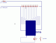
----- All Answer about the Dewalt 36V battery and B M S ---

thanks fechter!
ok so if the larger controller draws more amps than the batteries BMS can handle, then how many amps can i safely draw from the batteries?

I have 4 batteries in the circuit wired up as per the schematics on
http://www.neodymics.com/Images/V24ProtoSwitch070818E.pdf

Or the otherway around, how many batteries do i need to be able to draw 35A?

Also - this seems odd to me since some of the dewalt powertools are rated at 750W - this equates to about 20A - from one battery, I'm trying to draw 35A from 4 batteries - i.e. 9A each - am i missing something?

cheers,

Dean.
 
I think in theory you would be fine with the setup you have. I think the problem happens because the controller can draw way over 35 amps for just long enough to trip the BMS (milliseconds) under some operating conditions. The inductor is supposed to help avoid this.

I might have to refer to one of our DeWalt experts around here.
 
dean said:
I'm trying to draw 35A from 4 batteries - i.e. 9A each - am i missing something?.

If you wired them up per the schematic linked above, then the batteries are wired in a 2S2P configuration. You add voltage in series, current in parallel. When drawing 35A the batteries are giving 17.5A each at 72V. (Keep in mind that the 35A controller will allow peak currents above 35A). IIRC the fuse in the BMS is rated for 15A, so if you wired to the fused output rather than the switched output of the Dewalt pack, you might have just popped the fuse (this is repairable).

When you had the 20A controllers, did you have an in-line fuse? If so what amperage?
 
Thanks Fetecher / Ted for the input,

I'm wiring the batteries to the switched input, so the 15A fuse shouldn't be the problem.

With the 20A controllers i didnt use a fuse as I was under the understanding that the controller had it's own internal fuse, and each battery had one too (yes, I am an idiot).

So have i got this right - 72V @ 35A = 2520W. Divided by 4 batteries = 620W each, at 36V each battery = 17.5A each + current surges... is that how it works?

Ok so realistically i should be using 2s3p (for 11A each) or even better 2s4p (for 8.75A each).

really appreciate your help on this,
cheers,
Dean.
 
Dean,

Also realize that you never truly have 72V with these packs in series. Almost immediately after you place any load on them, the voltage drops to about 66V. When I run my fairly heavy 2-pac bike, even at five amps my sag is down to 62-63 volts. With more in parallel you won't sag nearly as much but still will not maintain a 72V potential.

So if you figure 35A at around 65V then you'll come up with say 2275W.
Your idea about adding more parallel circuits is the best way to reduce current draw per leg. One early concern about that was the possibility of unbalanced legs causing voltage to feed back into another set of packs. Not sure if anyone has explored or found any problems with that. It appears that quite a few people are running multiple parallel packs though. Just something else to think about.

JJ
 
I don't have any problems so far. :D I guess as long as everything is charged the same and depleted the same, your ok. I never would add a charged set in with some depleted ones though! But with fuses I would think that current would be limited to their value. Still, I wouldn't try it. :shock:
 
EMF said:
I don't have any problems so far. :D I guess as long as everything is charged the same and depleted the same, your ok. I never would add a charged set in with some depleted ones though! But with fuses I would think that current would be limited to their value. Still, I wouldn't try it. :shock:
 
oops i did have a message typed in there

anyhow, I since have had another design idea, i need 8 batts and would prefer to have them in the middle of the bike i am thinking of making those poly molds above 4our on each side with the wiring underneath.

2inchech apart like a saddle bag perhaps with an handle and removable

either fused ala emf or neo circuit


oh ya I remember any opinions on the neodymics circuits pro's and cons?

they should just sell the circuits for public testing . IMO

they must be ok , no?


4p2s board is it hard to make?

I know i can do the emf design thanks btw emf


efreak
 
Well, I copied that idea by reading about other peoples bikes, then made my own the way I wanted. I'm on to a new design now, (since it's snowing like heck every day) using the Mastech 5020e to charge with and the Bantam balancer for periodic balancing, mentioned in another thread by Microbatman.

http://www.rcaccessory.com/index.asp?PageAction=VIEWPROD&ProdID=191

I like his suggestions, so I will transmorgify them into something for my bike.

I've actually had my eye on this Mastech power supply for quite some time, and finally pulled the trigger.

This way, I can dump the Dewalt case and BMS, saving a lot of weight and space. Then I can fit more batteries into a smaller space too. I think I'll make another even simpler box, that lets me store these modified or stripped down ten cell units in compartments. I want to get at least a 20s4p setup on my bike and hopefully a 20s5p. If I could get a pack that would take me 30 miles without a charge, I would be a happy camper.

Maybe I can even set them in a different spot on the bike and get them off the rear carrier, I don't know yet.

I also plan to weigh my present setup and then my new one and see the difference. I hope I can get a lot more watt hours without a significant weight gain.
 
EMF said:
Well, I copied that idea by reading about other peoples bikes, then made my own the way I wanted. I'm on to a new design now, (since it's snowing like heck every day) using the Mastech 5020e to charge with and the Bantam balancer for periodic balancing, mentioned in another thread by Microbatman.

http://www.rcaccessory.com/index.asp?PageAction=VIEWPROD&ProdID=191

I like his suggestions, so I will transmorgify them into something for my bike.

I've actually had my eye on this Mastech power supply for quite some time, and finally pulled the trigger.

This way, I can dump the Dewalt case and BMS, saving a lot of weight and space. Then I can fit more batteries into a smaller space too. I think I'll make another even simpler box, that lets me store these modified or stripped down ten cell units in compartments. I want to get at least a 20s4p setup on my bike and hopefully a 20s5p. If I could get a pack that would take me 30 miles without a charge, I would be a happy camper.

Maybe I can even set them in a different spot on the bike and get them off the rear carrier, I don't know yet.

I also plan to weigh my present setup and then my new one and see the difference. I hope I can get a lot more watt hours without a significant weight gain.

You're on the right track. Dumping all vestiges of Dewalt's mess is a very good idea. Their BMS is messy and weak, and their charger is terrible. Most people keep the BMS just to use that nasty charger which doesn't balance well or at all many times.

The best way to balance A123 cells is not to use a balancer. Charge each cell separately, instead. Full is full, voltage isn't the whole story. So a balancer that discards and wastes charge (and battery life) to balance voltage isn't doing you a favor.

http://tinyurl.com/27eqxs

Folks in other discussions here have developed circuitry that does a great job of cell-level low voltage cutoff (LVC), the only function of the BMS you might need. Yet, if you build a pack with enough cells in parallel, protecting each other, then the standard per-pack LVC is probably enough. Assuming your charger tops off each cell or group of parallel cells.

Richard
 
I totally agree with Richard here, that balancing is not the real answer, but full charging for each cell is what you need. I'm still trying to fully understand what the heck really goes on, but one thing I know for sure is that in all my packs, each block of cells is "full" at a different level, even healthy cells. I have some that are weaker, and they get full at a lower level. The only way I can ensure that they get completely full is to individually charge each block of cells.

That said, I have one other setup that is completely different. I have five individual 16s single cell strings that only get paralleled for use at the sub-pack level. Normally, I connect all the cell junctions together, which connects the cells in parallel first, and then in series, but in this setup, I purposely left them separate. There's another thread here that I discuss this in, but basically I only charge these strings in bulk, as a 16s pack, with no balancing, or individual cell charging. So far, these packs will repeatedly take the same amounts back in, so I don't think they are grossly out-of-balance.

In any case, I think you are heading down the right path. Many in the RC world have used the 5020 to charge a123 packs with great success. I would just keep tabs on the individual cell voltages from time-to-time, to make sure they aren't drifting off too much. Actually, since the 5020 has an adjustable voltage control, from 0-50V, you could actually use it to individually charge an errant block of cells that managed to get a bit lower than the others.

As for fit, I was able to get a 20s6p setup, with two 10-cell LVC boards, to fit in a rack bag on my Townie:

ebikes-08.jpg


ebikes-09.jpg


-- Gary
 
GGoodrum said:
Actually, since the 5020 has an adjustable voltage control, from 0-50V, you could actually use it to individually charge an errant block of cells that managed to get a bit lower than the others.
-- Gary

This is what I have been thinking. Check the cells and if some get too far out of whack, I can take care of it with the 5020. I just need more experience/history. Darn winter.
 
120 cells! :shock: That would take you a long way if you stay under 25 mph I would think. I wonder what the length of that 6p string is?

Edit: Yes, you are really suffering! We already have over 12 inches of snow on the ground, with 2 more inches coming tonight. :cry:
 
EMF said:
120 cells! :shock: That would take you a long way if you stay under 25 mph I would think. I wonder what the length of that 6p string is?

Edit: Yes, you are really suffering! We already have over 12 inches of snow on the ground, with 2 more inches coming tonight. :cry:

Actually, I've since added a 4s6p "booster" pack in the bag up front, which gives me a 24s6p total configuration, or 80V/13.8Ah:

ebikes-11.jpg


I think the length of each 6p sub-pack in the bag is about 12-1/2 inches.

I'll stick with our fires and earthquakes. I don't do cold very well. :roll:
 
GGoodrum said:
EMF said:
...Darn winter.

Yeah, we're in the dead of winter out here as well. Although it is clear and sunny, It is only supposed to hit 70F today. :D:D I may have to wear long sleeves...

<sorry... couldn't resist... :)>

It's 76F at 10pm here. Lots of rain tho ... You guys can keep that cold stuff ...
 
I would like to make a lvc for my 20s2p a123 based pack, using 2
dewalt bms's.The 2 bmss should be activated by the resistor network
as in cyclemotor engineer's schematic, but the main current path would be directly
from the battery leads to controller bypassing the bms's. At the + e - terminals
of the bms I would connect two relays, that would activate in case of low voltage condition
of one of the cells, grounding the brake system of the controller .

This configuration should IMHO, avoid problems like one of the bms FEt blowing
for taking too much voltage (in case one of them opens and the other stays close)
and bulky inductors and skottky diodes.

Does anybody think this could work?circuit.gif
 
thanks Fetcher
now I just have to find the right relays. I don't think
they exist with a 36V rated coil, so I will use 2 24v with
a resistor in series
 
itron said:
I would like to make a lvc for my 20s2p a123 based pack, using 2
dewalt bms's.

My two cents: The Dewalt BMS is more trouble than it's worth. The Dewalt charger is total junk.

The BMS is a finicky, low-power black box that limits the A123 cells capabilities and does a very
poor job of protecting them.

The charger requires that nasty BMS to function and it does a terrible job of balancing the battery's
cells.

Folks on this list have designed, built and offer LVC circuitry that is much more robust and more
appropriate to the cells and application. A better charger can also make the LVC less necessary.

Don't use the Dewalt charger -- it's garbage.

Richard
 
agreed ! i've blow 4 bms till now .. i have 2 i can use but i refuse to for my setup b/c i know i will eventually damage them..
 
steveo said:
agreed ! i've blow 4 bms till now .. i have 2 i can use but i refuse to for my setup b/c i know i will eventually damage them..


Steveo, If you follow your rules, : "If you can't fix it; you shouldn't buy it" that don't make any sense that you've bought those BMS! :p

I'M kidding... 8)
 
Hi

I just paid for those 66w modules mentioned above. here is the data sheet

http://www.torontosurplus.com/tes/DataSpec/Tyco_QHW100F.pdf
and a good mutual freind has agreed to do me the favour of relay shipping (thanks Gary) I am happy with the prospect of this charger project because when finished it should allow for fast reliable and simple solution .

All I need now is ALOT of intructions from Doc ( I am lost !) but from the sounds of it should be easy enough to do

Thanks to the good members of this board who have been a great help to me and others either directly or indirectly

greatfully

efreak
 
Back
Top