Politbureau
New here
I've got a factory 20s11p pack with a woefully (and intentionally) underrated BMS that I am replacing, and could use a hand identifying in what order to swap cables etc. I'm ace at soldering and have a soldering station at home, but this is my first time wiring a BMS.
Old BMS is a JBD ZP series and new is a JBD SP series. I checked the wiring diagrams, and I can plug and play my balance cables to the new controller.
Here is old (L) and new (R)
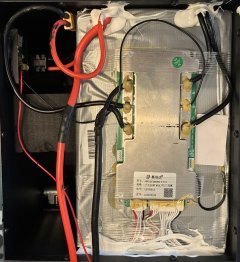 View attachment JBDSmartBMSSP24S0048S_24S200A.webp
You'll notice the OEM pack design has an DZ47-125A breaker inline with the output port ( ).
).
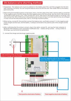
All the tutorials I've read indicate to:
Also - should I convert to ring terminals, or just solder directly? Thanks!
Old BMS is a JBD ZP series and new is a JBD SP series. I checked the wiring diagrams, and I can plug and play my balance cables to the new controller.
Here is old (L) and new (R)
View attachment JBDSmartBMSSP24S0048S_24S200A.webpYou'll notice the OEM pack design has an DZ47-125A breaker inline with the output port (
).All the tutorials I've read indicate to:
- solder L-R starting on input side (B-)
- insert balance cables
- solder L-R on output side (C-)
- connect and place the new NTM temperature sensor
- solder the charge and display cables
- 'wake up' the BMS by plugging in the OEM charger
- connect app to bluetooth to confirm pack string, AH, current and temperature protection limits
Also - should I convert to ring terminals, or just solder directly? Thanks!