Tube failure Calculation ?

qwerkus

10 kW
Joined
Jul 22, 2017
Messages
811
Hello,

I'm working on a custom CLWB and could use some help figuring out the seat tube strength. If I bolt the seat on a 36x1mm horizontal insert tube, what's the max extension possible before it starts bending ? Thanks for your help;
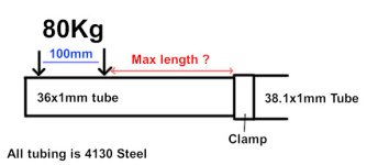
tubing.jpg
EDIT: Here my findings so far:

Area Moment of inertia of the inner tube: pi×(36⁴−34⁴)÷64=16850.717595692mm2

Using that value and applying a force of 1000N (roughly 100Kg) on 4130 Steel (E modulus of 205000N.mm-2), I get

deflection = 1000×L³÷(3×205000×16850.718), where L is the distance to the clamp in mm
max stress = 36/2*1000*L/16850.718)

so 10cm from the clamp,
deflection = 1000×100³÷(3×205000×16850.718)= 0.1mm
stress = 36/2*1000*100/16850.718=106.82 N.mm-2 or MPa

With a given ultimate tensile strength 540 MPa - I'm fine

Now 20cm from the clamp,
deflection = 1000×200³÷(3×205000×16850.718) = 0.77mm
stress = 36/2*1000*200/16850.718 = 213.64 N.mm-2
Still safe!

And based on a yield tensile strength of 460 Mpa, the max distance before the tube starts to deform would be
460×16850.718÷(36÷2×1000) = 430mm

At that distance, it would still bend down by 7.7mm, which is a probably a bit much!

Anyone getting the same results ?
 
Last edited:
Is this a horizontal tube to mount your seat on? Why not make it flexible so it can bend for a suspension seat post? Rattan comes to mind. laminated bamboo, wood? Leaf spring?
 
Is this a horizontal tube to mount your seat on? Why not make it flexible so it can bend for a suspension seat post? Rattan comes to mind. laminated bamboo, wood? Leaf spring
The angle of the top tube is around 6° so nearly horizontal; bike already full suspended - all I need for the seat tube is to take an adult weight without bending.
 
I am unaware that 36mm (1.417") OD x 1mm (0.039") 4130 tubing was even available - where did you purchase it?
 
I am unaware that 36mm (1.417") OD x 1mm (0.039") 4130 tubing was even available - where did you purchase it?
No idea - the welder had it in stock.

EDIT: 36x1.1mm is actually standart steering tube.
 
Last edited:
Cant help with the calculations or offer any engineering insights just a real world one.. I would not limit the mass to 80kg (your mass?) if the finished result is anywhere near a nice bike ( am sure it will be..) you can be sure your fattest cousin or their fattest pal will want to 'play' with 'your toys' ..
 
Couple of thoughts come to mind:

On a bike, as mentioned above, dynamic loading will be the main factor. A few bumps or a small jump could easily make 2x+ dynamic loading on the seat. Secondly, with a horizontal tube like that, it will bend as long as you are below the yield strength of the material... elastic deformation - it will 'spring back' to original shape. As soon as you go above yield strength, you enter plastic deformation where the material is permanently bent or deformed. Given a horizontal tube like that, hitting that point will likely mean a sudden collapse / failure / buckling of the tube. Lastly, be careful of what material strength you use for the tube calculations - and what state the material is in. I've examined several failures in alloy steel where the designer/manufacturer punched in strength calculations based on fully heat treated / tempered material. What they didn't realize was that the machine shop got fully annealed material (soft/weak) which is the easiest to machine/fabricate/weld, but then the finished part was never heat treated after manufacture, so never developed that 'textbook' high strength.
 
Using that value and applying a force of 1000N (roughly 100Kg) on 4130 Steel (E modulus of 205000N.mm-2), I get

deflection = 1000×L³÷(3×205000×16850.718), where L is the distance to the clamp in mm
max stress = 36/2*1000*L/16850.718)

so 10cm from the clamp,
deflection = 1000×100³÷(3×205000×16850.718)= 0.1mm
stress = 36/2*1000*100/16850.718=106.82 N.mm-2 or MPa

With a given ultimate tensile strength 540 MPa - I'm fine

I'm sorry to report that transient loads will screw your calculations to oblivion. Bump forces can exceed static forces by an order of magnitude or more. Whatever you think is adequate? Double it, then double it again, then double it again and you're probably okay.
 
Ineresting replies - thanks. Did some research, and was surprised that there is no exhaustive list of dynamic loads for something as simple as a bike frame: too many different scenarios. Nevertheless, the only relevant force in my case is the strongest one applied to my tube, which if I'm not mistaken is the reaction force in case of road bump and/or jumping onto the seat tube.

tubing.jpg

Next problem is finding a realistic value for that force; literature helps here and gives a magnitude of 3x, which is 3000N.

Using the stress formula from above, I get 460×16850.718÷(36÷2×3000) = 143mm max tube length. At that small distance the distance between the seat mount becomes more than relevant, so if I redo the calculation with two half loads separated by 100mm, i get:

max distance of the first seat mount point: (((460×16850.718)÷(18×1500))−100)÷2 = 93.543153333mm; second one 193.5mm

Interestingly enough, by using 1.5mm steel walls so 50% thicker, I also get around 50% more tube length:
(((460×24234.2)÷(18×1500))−100)÷2= 156.4mm

No idea if the clamp with hold though!
 
Tried Freecad + calculix today to simulate 3KN applied on the seat tube. Using a 45cm 36x1mm tube protruding by 250mm, I get a deflection of 3.21mm.
1.jpg
But von Mises are super high
2.jpg
If anyone wants to give it a try, I attached the freecad file.
 

Attachments

  • fem_sim.zip
    4.3 MB · Views: 0
Last edited:
Thumb theory suggests it's not quite enough material for the job.
Is a thicker wall available for 36mm diameter ?
Another possible solution is to insert a vertical spar inside the tube. (Like a wing spar)
There has been a few bicycle projects were this technique was the only solution.
Here are two artfully designed bikes built from thin streamlined shaped cro/mo tube where the only way to attain proper side to side stiffness in the main frame triangle was by inserting an internal strut. (Built in the 80's)

(The idiom rule of thumb refers to a tried-and-true way of doing something based on experience and not theory.)

2BlueJay's.JPG
 
Well my guts tell me it's too thin but I can't figure out a way to prove it theoretically. I guess my best option is to build a replica and attach weights to it until it deforms!
 
Look to light aircraft wing load testing for ideas on how to setup your test.
During my bicycle frame building career I would borrow bags of concrete from the local hardware store to build up the testing loads.
 
Back
Top