Fardriver controller serial protocol reverse engineering

Hello! Has anyone figured out the CRC16 calculation in the latest versions of the controller? I found this information: Poly: 0x8005, Init: 0x7F3C, RefIn: true, RefOut: true, XorOut: false. But it doesn't work for my controller. Here is one of the parcels, you can check:
AA 80 85 07 11 20 00 00 00 00 00 00 00 00 1F FF
AA 81 74 00 79 00 00 00 00 00 00 00 00 00 A2 5D
AA 82 00 00 00 00 00 00 00 00 00 00 00 00 C5 2A
 
Last edited:
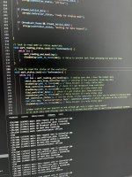
Making some progress with reading the UART from Fardriver controller. I am using an ESP32-S3, Visual Studio Code with PlatformIO extension and the ESP-IDF. I think i will have a working software at the end of summer.

20240623_215403944_iOS.jpg
 
Hello! Has anyone figured out the CRC16 calculation in the latest versions of the controller? I found this information: Poly: 0x8005, Init: 0x7F3C, RefIn: true, RefOut: true, XorOut: false. But it doesn't work for my controller. Here is one of the parcels, you can check:
AA 80 85 07 11 20 00 00 00 00 00 00 00 00 1F FF
AA 81 74 00 79 00 00 00 00 00 00 00 00 00 A2 5D
AA 82 00 00 00 00 00 00 00 00 00 00 00 00 C5 2A

This github repository has the implementation of the CRC in one of its files with some comments in russian. -> google translate.


But i think it´s only needed for sending data to the controller not for reading the data from it for a display.
 
The data there is outdated, I checked. The Chinese changed the algorithm again.
I just need a CRC for sending.
But I picked up the data!
 
I've started documenting my findings on the serial protocol in a Github repo - I've been able to decode most of the status messages received from the controller, and have started to figure out how to interact with the controller through sending commands, etc. I'd like to fill the fardriver.hpp with comments about what each variable does/how it works. The two CRC methods are described there are well.
 
Someone messaged me asking about details on what I've found, so I thought I'd describe the decoding algorithm a bit here, in addition to the readme I've been working on: fardriver-controllers/README.md at main · jackhumbert/fardriver-controllers - I also have the full decoding implemented in a 010 Editor template file: fardriver-controllers/fardriver.bt at main · jackhumbert/fardriver-controllers - it can decode a binary file of the data received.

The 16 byte status messages look like this (the c++ version is here):

Code:
0xAA <0x80 + index> <data[12]> <crc[2]>

Where the index (after removing the highest two bits) can be converted to a flash address via this lookup table:

Code:
const uint8_t flash_read_addr[55] = {
  0xE2, 0xE8, 0xEE, 0x00, 0x06, 0x0C, 0x12, 
  0xE2, 0xE8, 0xEE, 0x18, 0x1E, 0x24, 0x2A, 
  0xE2, 0xE8, 0xEE, 0x30, 0x5D, 0x63, 0x69, 
  0xE2, 0xE8, 0xEE, 0x7C, 0x82, 0x88, 0x8E, 
  0xE2, 0xE8, 0xEE, 0x94, 0x9A, 0xA0, 0xA6, 
  0xE2, 0xE8, 0xEE, 0xAC, 0xB2, 0xB8, 0xBE, 
  0xE2, 0xE8, 0xEE, 0xC4, 0xCA, 0xD0,
  0xE2, 0xE8, 0xEE, 0xD6, 0xDC, 0xF4, 0xFA
};

Based on that address, the data section can be mapped to a struct in the fardriver.hpp file, named via the address in hex: fardriver-controllers/fardriver.hpp at main · jackhumbert/fardriver-controllers - I tried to use a lot of the names from the app, but am still working on describing things/adding notes.

I'm also working on a template for HEB files that works the same way as the one mentioned earlier (HEB files are just pure data though, and also include CAN info): fardriver-controllers/HEB.bt at main · jackhumbert/fardriver-controllers
 
Hey,
Here's what I have been able to figure out about the serial communications protocol for the Fardriver controller.
I have only looked at the data FROM the controller, as I wanted to use it for a custom display.
My thread with my EKSR build that use that display, is here.
If you have anything to add to this and/or can help decode this further, please let me know.

Questions welcome, of course.

Here is a short Python program you can run to visualize the messages on the serial link and what bytes are being changed:
(change the serial port in the last line to suit your setup)

import serial
import datetime, threading, time

alist = [b'\x00' * 32] * 32

def open_serial_port(port, baudrate):
try:
global ser
ser = serial.Serial(port, baudrate, timeout=1)
print(f"Connected to {port} at {baudrate} baud.")
return ser
except Exception as e:
print(f"Error opening serial port: {e}")
return None

def clear_screen():
print('\x1B[2J')

def goto_line(line):
print('\x1B[' + str(line) + ';1H')

def set_color(inverse):
if (inverse):
print('\x1B[7m', end='')
else:
print('\x1B[0m', end='')
return

def read_from_serial(ser):
while ser.in_waiting:
try:
global alist
# read 16 bytes total : 0xAA, address, 12 bytes data and 2 bytes checksum
data = ser.read(16)
index = data[1]
if (index < 24):
goto_line(index + 2)
set_color(False)
print('{: >2}'.format(index) + ' : ', end='')
old = alist[index]
for i in range(2,14):
if (old != data):
set_color(True)
else:
set_color(False)
print(format(data,'02x') + ' ', end='')
set_color(False)
print('')
alist[index] = data


except Exception as e:
print(f"\nError reading from serial: {e}")


def write_to_serial(ser):
try:
data = input("Enter data to send: ")
ser.write(data.encode('utf-8'))
except Exception as e:
print(f"Error writing to serial: {e}")

def foo():
global ser
if (foo.first):
keep_alive = [ 0xF0, 0xF0, 0xF0, 0xF0, 0xF0, 0xF0, 0xF0, 0xF0 ] # size 8
else:
keep_alive = [ 0xAA, 0x13, 0xec, 0x07, 0x01, 0xF1, 0xA2, 0x5D ] # size 8
foo.first = False
ser.write(keep_alive);
#print (datetime.datetime.now())
threading.Timer(2, foo).start()

foo.first = True

def run_serial_terminal(port, baudrate):
ser = open_serial_port(port, baudrate)
clear_screen()
goto_line(1)
print(' 0 1 2 3 4 5 6 7 8 9 10 11')
print('\x1B[?25l')

timerThread = threading.Thread(target=foo)
timerThread.daemon = True
timerThread.start()

if ser:
try:
while True:
read_from_serial(ser)
time.sleep(0.1) # Adjust the polling rate if needed
except KeyboardInterrupt:
print("\nClosing serial connection.")
finally:
ser.close()
else:
print("Unable to open serial port.")

if __name__ == "__main__":
run_serial_terminal("/dev/tty.usbserial-834440", 19200)
 

Attachments

  • FarDriver serial messages.pdf
    157.3 KB · Views: 25
Someone messaged me asking about details on what I've found, so I thought I'd describe the decoding algorithm a bit here, in addition to the readme I've been working on: fardriver-controllers/README.md at main · jackhumbert/fardriver-controllers - I also have the full decoding implemented in a 010 Editor template file: fardriver-controllers/fardriver.bt at main · jackhumbert/fardriver-controllers - it can decode a binary file of the data received.

The 16 byte status messages look like this (the c++ version is here):

Code:
0xAA <0x80 + index> <data[12]> <crc[2]>

Where the index (after removing the highest two bits) can be converted to a flash address via this lookup table:

Code:
const uint8_t flash_read_addr[55] = {
  0xE2, 0xE8, 0xEE, 0x00, 0x06, 0x0C, 0x12,
  0xE2, 0xE8, 0xEE, 0x18, 0x1E, 0x24, 0x2A,
  0xE2, 0xE8, 0xEE, 0x30, 0x5D, 0x63, 0x69,
  0xE2, 0xE8, 0xEE, 0x7C, 0x82, 0x88, 0x8E,
  0xE2, 0xE8, 0xEE, 0x94, 0x9A, 0xA0, 0xA6,
  0xE2, 0xE8, 0xEE, 0xAC, 0xB2, 0xB8, 0xBE,
  0xE2, 0xE8, 0xEE, 0xC4, 0xCA, 0xD0,
  0xE2, 0xE8, 0xEE, 0xD6, 0xDC, 0xF4, 0xFA
};

Based on that address, the data section can be mapped to a struct in the fardriver.hpp file, named via the address in hex: fardriver-controllers/fardriver.hpp at main · jackhumbert/fardriver-controllers - I tried to use a lot of the names from the app, but am still working on describing things/adding notes.

I'm also working on a template for HEB files that works the same way as the one mentioned earlier (HEB files are just pure data though, and also include CAN info): fardriver-controllers/HEB.bt at main · jackhumbert/fardriver-controllers
Wow! Really nice work man! This is going to help my project a lot!
 
Someone messaged me asking about details on what I've found, so I thought I'd describe the decoding algorithm a bit here, in addition to the readme I've been working on: fardriver-controllers/README.md at main · jackhumbert/fardriver-controllers - I also have the full decoding implemented in a 010 Editor template file: fardriver-controllers/fardriver.bt at main · jackhumbert/fardriver-controllers - it can decode a binary file of the data received.

The 16 byte status messages look like this (the c++ version is here):

Code:
0xAA <0x80 + index> <data[12]> <crc[2]>

Where the index (after removing the highest two bits) can be converted to a flash address via this lookup table:

Code:
const uint8_t flash_read_addr[55] = {
  0xE2, 0xE8, 0xEE, 0x00, 0x06, 0x0C, 0x12,
  0xE2, 0xE8, 0xEE, 0x18, 0x1E, 0x24, 0x2A,
  0xE2, 0xE8, 0xEE, 0x30, 0x5D, 0x63, 0x69,
  0xE2, 0xE8, 0xEE, 0x7C, 0x82, 0x88, 0x8E,
  0xE2, 0xE8, 0xEE, 0x94, 0x9A, 0xA0, 0xA6,
  0xE2, 0xE8, 0xEE, 0xAC, 0xB2, 0xB8, 0xBE,
  0xE2, 0xE8, 0xEE, 0xC4, 0xCA, 0xD0,
  0xE2, 0xE8, 0xEE, 0xD6, 0xDC, 0xF4, 0xFA
};

Based on that address, the data section can be mapped to a struct in the fardriver.hpp file, named via the address in hex: fardriver-controllers/fardriver.hpp at main · jackhumbert/fardriver-controllers - I tried to use a lot of the names from the app, but am still working on describing things/adding notes.

I'm also working on a template for HEB files that works the same way as the one mentioned earlier (HEB files are just pure data though, and also include CAN info): fardriver-controllers/HEB.bt at main · jackhumbert/fardriver-controllers
Have you been able to figure out the login process via Bluetooth? I'm connecting to the the controller via BLE through my Mac and the controller seems to only send me dummy default values.
 
Have you been able to figure out the login process via Bluetooth? I'm connecting to the the controller via BLE through my Mac and the controller seems to only send me dummy default values.
Nevermind, messed up Little Endian with Big Endian!
 
Back
Top