18S LiPo Wiring diagram

mcclead2

1 mW
Joined
Feb 28, 2020
Messages
17
I am going to be building an E-Bike and have just ordered a BMS. I am an R/C Modeller so I have loads of 6S LiPo batteries which I plan to use in an 18S setup.

Below is a diagram from the BMS seller and a blank wiring diagram as I am unsure how to wire it up

Could anyone offer any advice?
 

Attachments

  • 18s lipo balance.PNG
    18s lipo balance.PNG
    89.8 KB · Views: 912
  • 18S Lipo Wiring.jpg
    18S Lipo Wiring.jpg
    44.9 KB · Views: 911
no.

No idea why you skip one, but don't do that.

On the balance plugs, each of the number 6 wires of the first pack, will be the number 1 of the next. So each pack, the last and the first wires of the balance plugs get paralleled. Its just like inside the pack, the positive of one cell is also the negative of the next cell in line.

In your diagram, 6 and the - connect together, and then both connect to 6, or 7 depending on the bms. The one you have labeled 8 is actually 7 positive, and connects to 7

I don't know about your bms, but in many, the negative connection is not a balance wire at all. The negative is the main negative wire of the pack. Then number one is the first positive balance wire, and so on.

That's the best I can say, without seeing the actual bms, or its wiring diagram.
 
Thank you dogman dan for you guidance

So my balance wire harness should look like this?
18S Lipo Wiring - 1 (1).jpg

Just waiting for some female JST-XH 6S connectors coming and I'll get it soldered up ready to test
 
mcclead2 said:
Thank you dogman dan for you guidance

So my balance wire harness should look like this?
18S Lipo Wiring - 1 (1).jpg

Just waiting for some female JST-XH 6S connectors coming and I'll get it soldered up ready to test

Lovely much better.
 
Eventually got my BMS and wired it as per their instructions - here is the diagram
18S Lipo Wiring - 1.jpg

Here is a screenshot from the BMS app
Screenshot_20200520-140850.jpg

Can anyone shed some light on this? I have tried different wiring combinations but nothing seems to work
 
From what I've seen over the years, BMS systems don't seem to be a good fit for RC LiPoly. If they can be made to work, they don't seem to last.
Some respond to this statement by saying a higher-end BMS is needed, but I'm dubious to this even.
I would suggest you either break the string and charge w/ RC type balance charger(s) or bulk charge w/ a power supply like a Mean Well HLG (although you can only get to 14S w/ this mode) and ck and balance w/ Battery Medics. Admittingly, not a solution w/out issues, these take time, but better than dealing w/ things that can result from BMS failure.
There are ways to monitor any LVC issues, the best being to carry extra capacity and watch a Voltmeter if a hard or programable LVC is not available.
Are you shooting for(w/ 6S bricks) 3S/1P or 3S/2P?
RC LiPoly bricks, especially as they get older are really dealt with best by a hands-on approach. If you honestly think about your experience w/ your RC devices, I think you will see the validity of this.
Since you are still in the planning stage, I would also suggest scaling back to 14S and pick a motor w/ a speed range that will get you to the speed you want. 14S can more or less be treated like 12S in terms of things like wire gauge, type of connector and blackened fingers:) A lot less pre-spark too.
I use big bricks these days, but when I used 6S stuff, I would build them into 2S/1P or 2S/2P modules and if I needed extra range, I would carry an extra and physically unplug and plug in the other one. W/ either 5000 mAh bricks or 10000 mAh bricks, I would get 14S by spliting a brick and adding a pair of cells for 6S + 6S + 2S = 14S.
 
The voltages are not true as I have charged and balanced them with my Thunder Power charger. Admittedly these are older packs I'm using to test the BMS with, so if it goes wrong I dont mind!

I was planning on using 3 x 6S lipo maybe 10000/20000 mah depending on space in frame

I might have to scrap the lipo idea and invest in li-ion packs or just take out of bike and charge with my r/c chargers

Thanks for the advice - it would be great though if I could get the BMS to work as I could balance 3 x 6S lipos for my scale models too! :)
 
Better to experiment with known-good fresh packs.

And better quality BMS looks like.

Wire up so easily removed / replaced, can use balance charger, checkers etc.
 
Should I include the negatives of packs 2 & 3 into the BMS wiring?

I am wiring the packs in series so if I connect the negative balance wire of pack 2 to the positive of pack 1, as well as having the discharge leads wired for 3 packs in series I would get a short circuit?
 
I believe as dogman said I stop using BMS a time ago. But last wire from one and the first wire from
pack two share the same channel and the last wire from pack two and first wire from pack three share the same channel ? Somebody will chime in on this soon. So check first. Because I didn't say these. I believe methods is the best one or ? He made things for lipo.
 
I see some misinformation in this thread.


First - there is absolutely no intrinsic issue using any "BMS" with hobby type packs. A 6S hobby type pack is nothing more than 6 cells in series with the interconnects pulled out on a JST-SM-7 connector. That will resolve exactly the same as a string of 18650's or anything else. There is no difference. . . other than the fact that you need to daisy chain the positive of the top of one pack to the negative of the bottom of the next.

Since the top and bottom balance taps are the same as the primary Positive and Negative, the act of putting the power leads of the pack into series satisfies the "missed" balance tap pin. . . hence why the screen shot of the BMS appears to be functioning properly (i.e. it looks from the diagram like balance pins were missed, but those electrical connections are satisfied by the connection at the power leads from the positive of one pack to the negative of the next)

Lots of things can go wrong. . .

There may be poor quality BMS's

There may be BMS's wired incorrectly

There may be corroded balance taps

There may be loose or pushed back pins in balance taps

Lots of things can cause a poor experience.

As for going it the "RC Way" - it is totally fine to use whatever RC Knowledge is already in hand. . . like breaking down the ebike pack and charging the RC packs one by one. . . BUT ... once you get into bigger systems, like 18S with two packs in parallel, totaling 6 RC packs. . . you are much more likely to make a wiring mistake.

...

First step, before doing anything, is to get the wiring pictures CORRECT.

I see a Screen shot showing a BlueTooth app reading all the cells. Another member asked "IS THAT CORRECT". What they were asking is if the information reported by the BMS is the same (to within 5% or 10%) as the information reported by another tool or DMM.

If that is true, then the BMS is wired correctly (enough)
(Tho ... if primary wires open between packs the... BMS inputs will take the brunt of it... by seeing full pack voltage across one input that is intended for only 4.2V max)

-methods
 
Plug in a standard 6S "RC Pack Checker" and write down all the cell voltages.

Alternately, you can check them with a DMM, just be careful because it is easy to short out the probes.

That will tell you if the 4.6V is a bad reading (due to 3-5 things) or an actual reading. Individual cells can absolutely get charged up to 4.6V. More likely it is something silly.

Each BMS input will have a "Clamping Diode". This will be something like 4.6V or 5V... so if you see a reading like that it may be an "Open Circuit" reading - or - a reading where you have a wire missing. In this case what is happening is the Open Circuit voltage of the pack is developing over that single channel, then getting clamped down to an arbitrary (but high) voltage via the protection diodes.

Depending on the size of the protection diodes, this may or may not cause damage.

...

If you blow the protection diodes (because they are under-sized) then the ADC inputs of the BMS will be damaged.

There are usually "light" protection diodes on the BMS chip core, and supplementing those, some heavy (high power) diodes right across each cell.

The primary purpose of these diodes is to protect from the following scenario:

1) User wires up pack as shown in final picture
2) Primary leads open while load is attached resulting in full pack voltage across single cell

In that case, the clamp diodes yank the signal down to 5V or 4.6V or something like that. . . to protect the BMS

Make sense?

That is my best guess at what that 4.6V is. Either an actual high cell (unlikely) or an open (ghost voltage) or a miss-wiring.

-methods
 
I did not look at the BMS screen close enough
(I always focus on the wiring first)

I would disconnect the pack from the BMS and confirm the resting voltages of the cells and that the wiring matches the definition of "correct".

I presume cell 8 is red because it is discharging or the highest "normal" cell
I presume the algorithm may be ignoring cells outside of "normal" range

Cell 14 is high and 15 is low, that is an indicator
Cell 17 is low and 18 is high, that is an indicator

Since the 4 spots that are reading funny are co-located. . . that is a strong indication of miss-wiring

...
The protection diodes and input capacitance play funny games with "passing along" ghost signals. Just because a voltage is being read does not mean that anything is actually hooked up to that particular input. For instance, if you wire cells 6 and 8, it is highly probable that cell 7 (even if disconnected) will read something arbitrary. .. just due to leakage current charging up ADC input capacitance

Most ADC's on something like this will have a LPF (Low Pass Filter)
That is a resistor inline with a cap
A cap is an Accumulator. . . so any stray current (leakage current) can accumulate on that cap resulting in a "false reading".

A false reading is a "ghost voltage"

-methods
 
A lot of that went over my head

methods said:
That will tell you if the 4.6V is a bad reading (due to 3-5 things) or an actual reading.

Besides the "what else could be wrong" factors?

Is the wiring diagram the OP came up with correct?
mcclead2 said:
Eventually got my BMS and wired it as per their instructions - here is the diagram
kY0dhp6.jpg

_____
Also, I hadn't come across JST's SM line before.

Looks quite similar to the XH line I believe usually used in RC LiPo's.

Are their pro's and cons? Do they interoperate?


(I am doing other things - posting to this between them)

Now that we went over basic BMS architecture that can cause those ghost readings (protection diodes, stray current, accumulating caps) - here is my high level analysis:

Everything looks fine right up to cell 13, then cell 14 is reading high and 15 low.... then later 17 is low and 18 is high.

This does not land right on a Pack-Break. . . (which is a common trouble area) and cells 17 and 18 are reading funny... so all "funny readings" are on the top most RC pack.

My first inclination would be to test that top pack and confirm that it is not in actuality fubar.
If the pack is FUBAR, good. No problem, balance it and try again very carefully (watching heat)
If the pack is not fubar, good. May be wiring.
If the pack and the wiring show up fine. . . then it can be damage to the BMS

* Input Diodes can be failed short(ish)
* Input Diodes can be failed open(ish)
* ADC can be damaged

The way I test that is to run the DMM up the line of inputs and get the arbitrary reading. If there is one that stands out as "different" that is a place to start looking. It is a hard measurement to take tho, because the input LVC will accumulate the measurement current from the DMM. . . resulting in a "false read". Generally what you do in this case is

* Crowbar the input
* Take the reading
* Take the reading backwards

Do this for all 18 inputs and write down the arbitrary measurements. You want to use a GOOD DMM... something like a Fluke 87V. Poor quality DMM's will not resolve as well, may drive greater measurement currents, may be more affected by stray current, etc. The Fluke DMM's run a really good algorithm that averages and filters out noise.

...

Short of all that

Put it in a box and bring it over to my shop.
Have that resolved in an hour.

-methods
 
Hey John

Yea... other things could be wrong for certain.

... As far as the diagram, I did not look super close. I will do that now.

-methods


john61ct said:
A lot of that went over my head

methods said:
That will tell you if the 4.6V is a bad reading (due to 3-5 things) or an actual reading.

Besides the "what else could be wrong" factors?

Is the wiring diagram the OP came up with correct?
mcclead2 said:
Eventually got my BMS and wired it as per their instructions - here is the diagram
kY0dhp6.jpg

_____
Also, I hadn't come across JST's SM line before.

Looks quite similar to the XH line I believe usually used in RC LiPo's.

Are their pro's and cons? Do they interoperate?
 
Per the request, I have confirmed that the diagram on the left is electrically the same as the diagram on the right.

methodsCheck.png

I do not have the hardware in front of me
I have not confirmed the wiring colors of the balance taps
I just went pin for pin to confirm. If hardware was here we would "ring that out" - with the DMM set on the Beeper function, carefully and thuroghly.

-methods
 
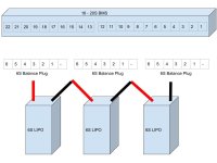
The person who made the original BMS wiring doc used BLUE to call out things which require double wires and black to call out the most negative.

There are any number of reasons for "funny wiring".
Looking at that BMS, it looks as if it were function-built for a specific purpose. Someone then adapted it to "general use". That explains funny wiring.

As to why a pin would be missing. . . and other pins doubled... eh....

The top most positive pin being duplicated is not a surprise. One of those pins probably goes to a voltage regulator that pulls on the entire pack voltage to create the 5V or 3.3V that drive the internal chips. You may be able to open/close one of those two to put the BMS into a low power mode.

Pin 11 being opened... eh...
There are 8 cells below that
The BMS can run 16 to 20 cells
Half of 16 is 8...

Generally if you do not use certain pins those get shorted. They would be all the top pins, as seen with pins 22 and 21 on the BMS. It may be that the software has a weird algorithm to treat the pack as 18S or 16S in the event that certain channels are wired open. Dont know - would have to see the Open Circuit voltage.

Generally speaking a BMS that is double layer like that - actually works! Nobody is going to put that much effort into something that sucks.

THAT SAID

If you got it for $20 some place. . . it may be 3rd hand. In this case there was something like a bad run at the factory. THen some guy bought all the bad run from the dumpsters for $1 each. Maybe one part needs to be fixed - whatever - some fix that is not worth the rework at the factory.

Then this guy... he sells them 20 at a time with a note on what needs to be fixed. Some people fix it, some people dont. Maybe they sit in a box for a year.

Then some other jerk finds them. Does not understand what he has or that it has a RED TAG issue, and wants to make a quick buck. Maybe he does not do the rework and just sells the stuff. With or without the fix document.

Or... Maybe the fix document was in Chinese and that did not get translated

Or... :)
Where was it purchased?

I only purchase things from Amazon Prime, Hobby King, etc. I never buy direct from China unless it is from a known good supplier.

Sometimes I buy from Battery Space or a few others. . . but only reputable people who assure good running. I.E. I do not think methods over here has ever bought an Ebay SPecial.

Not that I would hesitate... jsut... I know how things like that GET on ebay in the first place. It is almost always RED TAG stuff (manufacturing rejects) - and those may or may not have good rework.

Open it up and look inside. Do you see signs of rework?

....
Or maybe it just really is good factory stuff going out the back door. Never know.

Good luck guys, going back to working hard for no money.

-methods
 
john61ct said:
Appreciate your responding so fast methods. . .

Anything I can do
I only come over here when someone points out a question to me. :bigthumb:

I answer in bursts from the hip.. because if I do not... then I never get it done. I used to have lots of time to ponder this stuff and work up detailed and complete thoughts... but these days... I am super busy trying to make a dollar out of 15 cents.

Made a Waterproof Battery Housing

Jump.png

and then another

IMG_20200512_154823.jpg

-methods
 
Final thought

I have been a practicing Electrical Engineer for 20 years post bachelor, including being a Tek. I know every aspect of troubleshooting (hands on or remote) as well as the detailed design and algorithms of BMS design. I.E. I could make that BMS.

When I started here I did not even know what a lithium battery WAS... and all of that is chronicled. All the lessons we learned along the way and how we learned them. ... guys like Fechter taking the and Garry taking the time to teach...

Guys like me want to help. . .

But often we dont come around because folks get an attitude. It causes great stress.

Someone who has deep knowledge on a subject just does not want to spend time sparing with people who just want to argue.

...

An Engineer will gladly "defend" statements of fact, especially if they are pointed questions. Things that can be resolved as True or False, or logical or illogical.

BUT

As far as the ... I dont know... the... "Bar talk" that happens. The dick swinging of laymen... that gets real annoying. There are laymen who really put in the work to understand things and they offer help and ask for help. I love working with them, seeing them learn.

Then there are people who are just obnoxious - like - either they just want to argue or they somehow expect to understand or be spoon fed highly complex concepts... and... meh.

I rarely have a good experience over here anymore. Not for years.

... after a while guys like me just go into our own thread and just work open source. Even then, other people come and complain and insist that things are not refined enough for them... as if we are here specifically to feed them final solutions.

meh

If the board wants free Engineering Support then it is available - but - there is a certain culture that has to be maintained. Guys like Fechter embody that spirit.

-methods
 
Back
Top