ridethelightning
1 MW
- Joined
- Jul 21, 2013
- Messages
- 2,010
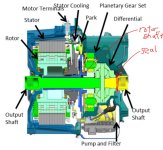
thanks hh, but not quite direct drive.
driving the tailshaft to the diff which is 3.5/1 ratio I believe.
I am also going to be using lower voltage, `~150v, possibly 300v if i reconfig the cells, so this may also make it less efficient with lower rpm??
I could also keep the spark stock gear assembly.
driving the tailshaft to the diff which is 3.5/1 ratio I believe.
I am also going to be using lower voltage, `~150v, possibly 300v if i reconfig the cells, so this may also make it less efficient with lower rpm??
I could also keep the spark stock gear assembly.
")