
You are using an out of date browser. It may not display this or other websites correctly.
You should upgrade or use an alternative browser.
You should upgrade or use an alternative browser.
== 2100Wh 432 konion MAKITA cells project == 16 june 2008
- Thread starter Doctorbass
- Start date
Doctorbass
100 GW
jeffkay said:Hey Doc, See my A123 sub-pack for "Deep Cycle"... That is #4 ga. solid in a "J" shape.
That's heavy cooper rod you have!!!
Are you sure that the amounth of heat to solder them to each tab did not dammaged the cells?
see what A123 racing worte here:
http://www.rcuniverse.com/forum/m_5025604/tm.htm
cooper keep heat for long time!!. I agree that the max current they can give will be availlable thru that heavy rod!! but i hope your cells ketp their good health agter soldering! there are many post on many forum that claim that heat have dammaged their cells!... so in regards of that, how did you proceeded?
Doc
jeffkay
100 W
- Joined
- Sep 14, 2007
- Messages
- 115
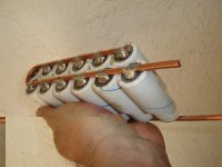
Two methodologies in my construction: 1. 80 watt iron 2. torch! Big one. The torch is only used on the positive (large) face--you will notice the small disc loosen during tinning. The big rod is HELPING--size does matter... More later. So first I use the iron on the neg (small side) ad QUICKLY tin it using much solder (for heatsinking and for flowing later to the rod. Then the torch is used to tin the bottoms. Obviously finesse must be learned as I did cook a few cell while coming up with the system... I suppose if I had a bigger iron it would do--well actually, the 80 watt iron does one or two fine but then starts to cool down and you must wait for the iron to heat up again. So I am impatient. After tinning I immediately blow (mouth) on them. This seems to suffice. Some guys use water and sponge. The extra solder is a heatsink, a good conductor to the solid wire and a moneysink. Oh and lead is heavy...I got over it. Next comes the solid wire attaching. The "J" shape is laid on top of the cells (just taped together, some guys use crazy glue). I work from the two ends inward as I finish soldering. The solid wire conducts the heat to the next cell, preheating it. AND this heat transferring makes it harder to damage the cell. Be sure to get the solder to flow without cold joint!
The 4 ga. wire has several advantages. It is structurally holding the cells firm in the "ladder". The 4. ga wire is available at Lowes and Home Depot for about $25 for a coil of 25 feet! This is very good price. Interconnecting the sub-packs is easy--after stacking the sub-packs next to each other in the opposing polarity to create the series string, you simply bend over the wires to be next to each other and solder. The end termination is very neat: I take a hex nut for threaded rod--these are about an inch and a half long in the 3/16" size. I drill a hole longitudinally through the nut towards one end (leave a bolt inside during this step to keep the solder from going into the threads and backing the end near the hole. Fill with solder and now you have a great termination to use for external cabling. I will post some pics later. So far this is a great system with no problems. Yes, you must be careful not to overheat the cell ends. I just used my pack to WELD with using a portable MIG spool gun! The "Deep Cycle" conversion motorcycle is setup for 150-220 amps and the A123's perform well with the packs staying cool. The bike is described here in detail: http://www.evalbum.com/1617
Note: there has been talk of the "vents" on the negative terminal. The vent s not in the center--that is just a rivet. I suppose some venting can emit here in an emergency but the real venting occurs under the terminal where there is a plastic interface. So I bring this up because I solder over the rivet and have test vented a battery and it came out the plastic area as expected. The point is I don't believe covering the rivet to be a big deal...
Jeff K.
Doctorbass
100 GW
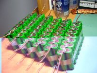
I've assembled 3 more group this morning. it tahe around 1h per 1s16p to assemble.
I first need to cut the nickel trip to seperate each selected cells in the original 4s makita pack. I use my dremel. that'S a great tool for that!
Then, i need to remove the small edge on the strip to avoid possible short circuit...
-I place all eight 1s2p cell group together and i tape them for the next step.
then i solder the cooper wire to all neg strip.
After that i measure all cells to endure they are all charged. i case where one or more would not be charged, that would dammage them caise the charging current from the others cells would be very high! 40-50A... I need that all cells have at least 4.100V.
then i solder the positive cooper wire.
and that's done!.. I proceeed to the next
Here are the 6 first pack: from now i assembled 480Wh... and that look very small!
Attachments
Doctorbass
100 GW
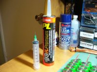
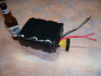
First full pack (10s) assembled!.. I just need to fill all the space between cells with the PL premium bulldog Grip to ensure they stay together and des'nt move!
But before i will re-test all individual 1s16p pack to ensure thet respect all the predicted capacity and RI.
So I need to charge all them to the same SOC . For that i wired all them in parallel and after that i will leave them alone for at least 8h.. and finally i will dishcarge them with my CBA 2 at 10A and doublecheck if they meet the previously calculated value.
After that i will glue all these 16 cells per pack together with the bulldog grip.
i'll have half the total power! at least 37V nom 42Vpeak at 23.8Ah 10C.
Doc
Attachments

Doctorbass
100 GW
jeffkay said:Doc, Are you sure you want to goo up those cells with adhesivo? Seems like an unneeded step. What kind of housing/skin are you planning for the bike?
Jeff K.
I plan to use a box made of sheets of 3/32" thick of white fiberglass.
I want to be sure all cells will not move together and that a spotweld could broke and isolate one or more cells from the pack. I want a perfectly balanced pack in capacity!... Often, what happen with multi parallel cell pack is that a spotwelded cell tab broke. and that make the pack operation with one less cells.. that cause imbalance in pack capacity and dammage the pack after few next uses...
From now, i wonder if i built 2 large prismatic pack that i will place at the rear rack (30 lbs of battery for 1.8kWh)...
or if i try to seperate each of the two pack in multi 1s pack that i place on every empty space availlable on the bike to share the weight.
for 2 prismatic pack located on rear rack, the pros is that all the 1s pack will be together and the temp sharing will be perfect due to tehe same box that enclose all them.
the cons is that i will have 30 lbs located at rear.. and that will be not suitable forthe driving stability!
For the multi 1s shared on any empty space on the bike, that's the opposite.
no of these solution seems to be the best... :|
Doc
Link
1 MW
Showing off that much lithium is just rude. Have some decency, man.
:wink:
:wink:
Doctorbass
100 GW
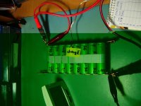
I am now testing each individual pack using the CBA-II.
I'm very impressed about the results!
I first charged in parallel each group to 4.198 and i left them for few hours to stabilyze.
After that each of the 10 groups showed 4.196V exactly!!
I also stabilyzed the room temperature between 28.6 and 24.8 degrees C
Then i began the diacharge test at 15A that is fast and that keep enough accuracy on the Ah measurement.
I sometimes, i needed to open the door, or the windows, or to turn off my monitor to avoid overshoot on the temp!.. that's a real DIY Battery test LAB !! :wink:
From now:
I got:
1 23.12Ah
2 23.35Ah
3 23.26Ah
4 23.18Ah
5 23.13Ah
6 23.21Ah
7
8
9
10
I suspect that the connection between the cells and the CBA-II wires may introduce some resistance that cause Ah to have some error dur to the V loss...
My theorical predictions was:
Pack 1 :Cap= 23.12
Pack 2 :Cap= 23.12
Pack 3 :Cap= 23.12
Pack 4 :Cap= 23.11
Pack 5 : Cap= 23.12
Pack 6 : Cap= 23.12
Pack 7 : Cap= 23.10
Pack 8 : Cap= 23.11
Pack 9 : Cap= 23.11
Pack 10 : Cap= 23.11
again some pics:
Doc
Attachments
Doctorbass
100 GW
The graph result of the sub pack 1 to 10 results:
jeffkay
100 W
- Joined
- Sep 14, 2007
- Messages
- 115
Hey Doc, How do I statically measure the resistance of my A123's and figure out the capacity or life?
Jeff
P.S. Good work on your matched pack! I have a CBA2 and had to mod it also. Do you find the voltage reading is off from a metered reading?
Jeff
Jeff
P.S. Good work on your matched pack! I have a CBA2 and had to mod it also. Do you find the voltage reading is off from a metered reading?
Jeff
Doctorbass
100 GW
jeffkay said:Hey Doc, How do I statically measure the resistance of my A123's and figure out the capacity or life?
Jeff
P.S. Good work on your matched pack! I have a CBA2 and had to mod it also. Do you find the voltage reading is off from a metered reading?
Jeff
Hello Jeffkay,
The CBA 2 does measure the capacity.
For the internal resistance of the cell measurement, they explain a great way to do that. in summary, you only need to measure the voltage drop with and without load when the discahrge curve is enough flat ( not at the beginning or at the end of measurement)
then by knowing the discharge current you do some math: R = (V no load - V loaded) / I
Then you will het the internal resistance. or go to the help in the CBA software.
About the voltage drift between the cba measurement and the real voltage of the cell, that's due to a bad desing of the CBA. it loss voltage in the wires dur to their resistance.
the CBA engineer should built a new version with 4 wires sensing!!! like i did when mooding my megapower charger.
This megapower nice charger do the RI measurement automaticly. at 3minutes of the beginning dishcharge process, it cut the load and compare the volt reading no load to the previous with load.. and it does the math...
The CBA volt drift is a bigg problem i think!!!
I wrote to the cba sales dep to explain that. .. still no answer...
Doc
Doc
VRdublove
100 W
Where can I find these at $4/Cell? I'm assuming there are ten of these cells in the Makita 18V, 3.0 Ah pack, is that correct?
Doctorbass
100 GW
VRdublove said:Where can I find these at $4/Cell? I'm assuming there are ten of these cells in the Makita 18V, 3.0 Ah pack, is that correct?
search for lithium manganese li-ion cell
batteryspace, battery universe..etc..
I sale them used but under 100cycles done for 25$each you get 8 good cell out of 10.
10C 1.5Ah x 2 parallel x 5 serie (original pack)
pm me
VRdublove
100 W
I got ahold of some of the Makita 18V 3.0 Ah Lithium-Ion packs today. Unfortunately, they use 4 hard-to-find security torx screws to hold them together. I might have to order the security torx driver online, as the bits are too wide to fit in the holes. Do you happen to know what size it is Doctorbass? Is it T-15?
Doctorbass
100 GW
VRdublove said:I got ahold of some of the Makita 18V 3.0 Ah Lithium-Ion packs today. Unfortunately, they use 4 hard-to-find security torx screws to hold them together. I might have to order the security torx driver online, as the bits are too wide to fit in the holes. Do you happen to know what size it is Doctorbass? Is it T-15?
I use the torx bit and my drill, but like you said, the hole is a bit too small so i pre-drill a larger hole before.
this is the T-10 torx.
You can buy a bit kit on ebay fot less than 7$.. search here it is a post about that!
(search : dewalt torx)
Doc
Doctorbass
100 GW
========== Update 13 may 2008 ========
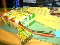
While working on many ebike project at the same time I finished the first pack out of 4.
522Wh 6s18p
- 22.2V
- 23.5Ah
The first one built always take more time to built than the next one...
Here are some great pics for you guys:
While working on many ebike project at the same time I finished the first pack out of 4.
522Wh 6s18p
- 22.2V
- 23.5Ah
The first one built always take more time to built than the next one...
Here are some great pics for you guys:
Attachments


VRdublove
100 W
That looks great!
Question: What do you think caused the failure in the original pack? Do you think that it was thermal management? If so, what are you doing differently with this pack to make sure that it doesn't happen again?
Also, can you explain what the Yellow wires are for? I was thinking it was to balance each pack that is in series, but there are 7, not 6. And why do you have two positive and two negative leads?
And one more thing, what is the best way to remove the old tabs off the cells without bending or damaging the cells? Sorry if these are silly questions, I'm just new to packbuilding and I want to make sure that I do mine right.
Thanks and good luck with the next one!
Doctorbass
100 GW
VRdublove said:That looks great!
Question: What do you think caused the failure in the original pack? Do you think that it was thermal management? If so, what are you doing differently with this pack to make sure that it doesn't happen again?
Also, can you explain what the Yellow wires are for? I was thinking it was to balance each pack that is in series, but there are 7, not 6. And why do you have two positive and two negative leads?
And one more thing, what is the best way to remove the old tabs off the cells without bending or damaging the cells? Sorry if these are silly questions, I'm just new to packbuilding and I want to make sure that I do mine right.
Thanks and good luck with the next one!
Alot of questions here!.. I like that :wink:
What cause the fail of the makita pack is always the same thing!.. as i mentioned earlier in the previous post about the makita, the problem is the bad spotwelding quality combined to the first pair of cell
place that is subject to more vibration than the next pairs.
Now, in the new generation of Makita LXT pack, they have 4 spotweld instead of two. that solve the problem. So every pack i have have the first pair of cell deffect and the next cell are great.
in my pack project, the yellow wires are for charging. i'll use my multi dc-dc charger to charge this 6s pack. I need 7 wire to charge these 6 s sub pack in serie like many 6s balancer have 7 wires.
Also, i had availlable alot of AWG 10 wire that is able to hold 55A in short lenght so i've installed two of them per polarity to hold the 90A of my controller, for 110A per pair and hum motor
The best way to remove the strip from the battery tab is to use cutter that you twist the strip closer to the spotweld to pull on it. then you rotate the strip from the cell for the next spotweld.
to seperate the cells, i use a dremel. but i dont recommand to seperate the cell pair that are matched and that have the same lifetime.
About the thermal management of my pakc, i carefully choosed the older cell and placed them in the surrounding of the pack (at both of the end of each subpack), so the hest that is always more intense in the middle will occur only to the younger cells and their cycle life should decrease equally around the entire pack.
Doc
VRdublove
100 W
Good deal. Thanks for the help! I somehow managed to come up with a few more.
1. So for charging these you are running 1 positive wire to each 1S of the 6S, and then one negative wire to the middle of the 6S?
2. Is there any easy way to get the white plastic bracket out of the original pack without separating the paired cells? I have been using a razor blade, and that has been a real hassle.
3. Is there any way to measure the capacity or age of a cell with a typical multimeter?
4. So if large enough leads are used, only one lead per polarity is needed?
5. What dc-dc converter would you recommend?
Thanks again!
Doctorbass
100 GW
VRdublove said:Good deal. Thanks for the help! I somehow managed to come up with a few more.
1. So for charging these you are running 1 positive wire to each 1S of the 6S, and then one negative wire to the middle of the 6S?
I run two positive AWG 10 wire to the most negative of the 6s battery, and two AWG 10 wire on the most positive of the battery. then one 14AWG wire to each 1s positive including the last most positive and the first most negative for a total of 11 wires
2. Is there any easy way to get the white plastic bracket out of the original pack without separating the paired cells? I have been using a razor blade, and that has been a real hassle.
no, the way i use is to cut with a dremel the negative strip of each linked pair of cell. that is not too long because you have to cut each pair for others anyway.. so it's only an additional cut. Then i use a spacer that have the same space between cells than original and i place it between both cells close to the negative end and i solder the cutted strip. The cell pair is now re-assembled.
3. Is there any way to measure the capacity or age of a cell with a typical multimeter?
no, because what you need is a constant current load. then to measure the voltage at mant time step... or just buy a watt's up meter on ebay (some RC compagny sale them.. they cost 55$ and will display the Ah and Wh... so you would only need a load resistor with a device or circuit that cut theh dishcarge at ALWAYS the same cutt-off voltage (a LVC circuit)
4. So if large enough leads are used, only one lead per polarity is needed?
Yess, but the reason why i used double lead is that on 18p subpack, ALL CELL NEED TO DISCHARGE AT THE SAME RATE.. so the current that flow into each parallel cell IDEALLY need to be the same... that wil help for thermal management too cause these cells are sensitive to heat and their capacity at discharge vary dependint on temperature.
5. What dc-dc converter would you recommend?
Any DC-DC that are isolated between in and out, that are adjsutable between 3 to 6V (originally 5V) that will allow you to charge A123 nanophosphate cell at 3.6V AND lipo or conventional li-ion cell at 4.2V
Doc
Ypedal
100 TW
Hey Doc .
How do you open the 3ah packs ?... i have the security bit for the torx with dot in the middle for the 5 cell packs, but canot locate the right bit for the 10 cell packs.. did you just grind one down or have you been able to locate the right narrow bit ?
How do you open the 3ah packs ?... i have the security bit for the torx with dot in the middle for the 5 cell packs, but canot locate the right bit for the 10 cell packs.. did you just grind one down or have you been able to locate the right narrow bit ?
Dunhill_BKK
1 mW
- Joined
- May 26, 2007
- Messages
- 16
A gentle reminder Doc, you promised me pics of the disassembly of this type of pack.
Similar threads
- Replies
- 0
- Views
- 335
- Replies
- 10
- Views
- 966