You are using an out of date browser. It may not display this or other websites correctly.
You should upgrade or use an alternative browser.
You should upgrade or use an alternative browser.
3D printed 400mm EDF project
- Thread starter SkyersJet
- Start date
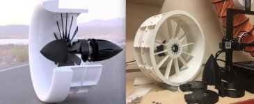
New Prototype
- Wider shaft to prevent flexing
Drive shaft secured at both ends to prevent vibration
Washout added to blades
Duct lengthened to allow air to accelerate
Thinner walls and shorter screws to save weight
Narrower gearbox to not obstruct air
Stators are now aerofoil sections
Nylon blades
Attachments
nicobie
100 MW
Nice.
Can't wait to see the test results.
Can't wait to see the test results.
SkyersJet said:New Prototype
- Wider shaft to prevent flexing
Drive shaft secured at both ends to prevent vibration
Washout added to blades
Duct lengthened to allow air to accelerate
Thinner walls and shorter screws to save weight
Narrower gearbox to not obstruct air
Stators are now aerofoil sections
Nylon blades
Seriously impressive project, might as well use it to propel a bike
But unless your nylon is higly CF/GF-filled, it is not that much stiffer than petg in my experience, so you'll still have problems with blades contacting the shroud at high RPMs I suspect. They might *survive* it though, but this is still not very nice...
Using CF/GF filled filament (not nessesarily nylon, CF petg works well according to my tests, to promote epoxy adhesion) and carefully gluing strips of uni CF to stiffen the construction over it will work, but balancing it would be a nightmare (I think it was already suggested).
SlowCo
1 MW
Yes I can see/view the video.
Did you also have a thrust measurement in place (suitcase weighting scale) to see the amount and difference in thrust?
Did you also have a thrust measurement in place (suitcase weighting scale) to see the amount and difference in thrust?
I could see the video too. At least it held together this time. Which one gave the most thrust?
[youtube]aXQasmUR1WQ[/YouTube]
PDF with more data and theory:
http://www.skyersjet.org/resources/(web-version)-The-Effect-of-Geometric-Pitch-on-Fan-Efficiency.pdf
PDF with more data and theory:
http://www.skyersjet.org/resources/(web-version)-The-Effect-of-Geometric-Pitch-on-Fan-Efficiency.pdf
mechhead
10 W
Hi, nice work.
you are likely loosing a lot of thrust because your diffuser thrust straightening fins are not angled and are likely in a stall. you might study pictures of ones off actual aircraft. the air coming out the back of the fan is turning about the aixs and this needs to be caught with angled fins that cancel the rotational moment of the airstream, a lot of the thrust is made by streightening the flow with angled stator blades that also have an optimal spiral twist to them and the duct nozzle is non parallel in most ducted fans also to enhance thrust .
keep up the experiments you may also like to try a pancake style drone motor that is made for the slower rpm of the big fan instead of a lossy gearbox an 80 or100mm dia one can be had inthe same power level as the motor your using
I tried angled fins, it was a flop https://twitter.com/SkyersJet/status/1496912610553483269
If you mean an outrunner the problem is torque, not power hence the gearbox.
If you mean an outrunner the problem is torque, not power hence the gearbox.
nicobie
100 MW
Is that strain gauge reading lbs.? If so 161 lbs is great!
nicobie
100 MW
That's still respectable! I was having trouble believing it could pull 161 lbs. 8)
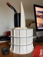
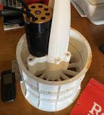
The SkyersJet EDF is back! (in a smaller version and unfinished). People have been asking for the files for about 2 years but I wanted to finish testing it. Due to cost I don't know when that will happen so I am just releasing files and instruction as I go along. If people are still interested I'll continue with it.
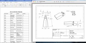
Files: 190 mm Electric Ducted Fan (EDF) by SkyersJet
This is still not the 400mm however, that has severe vibration problems due to bad tolerances and needs to be entirely rebuilt. This is a smaller version that's a) easier to print and b) I made a gearbox with proper backlash and tolerances this time (H8-f7). Some people hate the gearbox however so I may produce a direct drive version at some point. You can also do it yourself; not only are STL files included but carefully annotated 2D drawings of every dimension for reverse engineering.
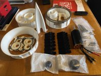
Two very important points: 1) If you somehow succeed at building it without a BOM and build video please take proper safety precautions i.e wear goggles and test it outside or in a safe room. 2) Do not print anything that hasn't been already supplied as a STL. That includes the rotor hub that the blades attach to. I wouldn't attempt this build unless you are prepared to buy some stock parts and have others machined. If you choose to rig it for direct drive then all you have to machine is the rotor hub and buy some screws. Should cost maybe £100. Use aluminium. If you stick with the geared version you don't have to machine the gears I provided links to suppliers of them but any will do so long as they are of the same dimensions and module.
Attachments
Bill of Materials (parts list) now available alongside additional part drawings. 180 mm Electric Ducted Fan (EDF) by SkyersJet
Attachments
Respected sir, please tell me how much rpm required to get 18kg thrust...?Hi, thanks for your interest! All of the data is summarised at the end of my videos. In the first video (thrust test 6) I recorded 20kg thrust at 7712W. In the second video (thrust test 8 ) I recorded 18.7kg @ 7471W. NB: Different scales were used for both tests + I think that the batteries were sagging by the time I switched scales so I don't know which result is more valid.
Respected sir please provide me it's rpm details when it reaches at 18kg thrust. @ 7200kw.Seriously impressive project, might as well use it to propel a bike
But unless your nylon is higly CF/GF-filled, it is not that much stiffer than petg in my experience, so you'll still have problems with blades contacting the shroud at high RPMs I suspect. They might *survive* it though, but this is still not very nice...
Using CF/GF filled filament (not nessesarily nylon, CF petg works well according to my tests, to promote epoxy adhesion) and carefully gluing strips of uni CF to stiffen the construction over it will work, but balancing it would be a nightmare (I think it was already suggested).
Respected sir, please tell me it's rpm details when it reaches at 18kg thrust.!Hi, thanks for your interest! All of the data is summarised at the end of my videos. In the first video (thrust test 6) I recorded 20kg thrust at 7712W. In the second video (thrust test 8 ) I recorded 18.7kg @ 7471W. NB: Different scales were used for both tests + I think that the batteries were sagging by the time I switched scales so I don't know which result is more valid.
Hi SkyersJetHmm must be my browser.
circular intake gave 5.7kg @1492W and the elliptical one gave 5.8kg @1439W
Great project!
I have been (subscribed) and watching your videos for ages.
I posted about the Optimal Elliptical Bell Mouth research on one or 2 of your videos. I assume you saw the post/s!?
They certainly look to be optimal in the pic in post #29.
A solution to Blade Strike on duct wall:
Applying an abrasive but lubricating compound as you slowly ramp RPM up should abrade away any longer blade tips and/or low points on the duct.
I'm thinking a good number of tiny holes (temporary) in the duct, just upstream of the blade tips, through which such an abrasive might be slowly pumped.
So that any point/s touching at X rpm are ground away.
Then once they are gone; you up the RPM to X+10 RPM etc-etc until all high points are ground away at the maximum RPM.
At his point you need to account for the blade movement that will take place when the ducted fan moves in space as it would on an aircraft.
ie: You need to be pumping in abrasive/lube while you turn the whole fan every which way at around the same rate at which it would move in an aircraft.
Any steps in the duct might be very carefully blended out after, by taping the ground away area to avoid sanding it more.
NB that the Science says NOT to use a sandpaper grit of less than 500 as that's the point at which skin friction becomes an issue. All the 3D printer 'lines' have been smoothed right..?
Alternately:
Dielectric Barrier Discharge (DBD) might be used to ameliorate reverse flow in this area and is as easy to test as hoops of aluminum foil and Kapton Tape.
See this and other posts on DC DBD etc here.
Last edited:


