48 Pole Torque PAS on a Cycle Analyst?

dirtdad

1 kW
Joined
Mar 2, 2008
Messages
309
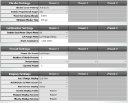
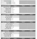
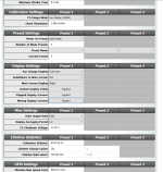
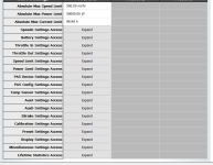
I have been happily using a Sempu torque-sensing bottom bracket hooked up to a Cycle Analyst, but the BB spindle rounded out and it is time for a replacement. Hoping to get a plug-and-play replacement, I got a Sempu BB on Aliexpress, which looks identical to my dead one. But Sempu upped the pole count to 48, and based on the signals the CA is getting, they went from a 2-wire to a 1-wire type.

Unfortunately, at least with my version of firmware, the most poles my CA supports is 32. If I enter 48 and save it, the CA changes it to 32.

Am I hosed? Is there a firmware change to support 48 pole torque PAS? Some other workaraound maybe?
 
It'll work with less poles, it will just think you are pedalling faster than you really are (because there will be more pulses counted than expected per rotation).

For easy math you can set the CA to 24 poles instead, so then all the related numbers you may want to set up will be an easy factor of 2 or 1/2.


Alternately you can just not connect the Sempu's cadence sensor and use an external one with whatever number of magnets (poles) you want, since the torque sensor portion is "independent" as far as the CA is concerned.
 
That’d be cool if there was a custom firmware that you could flash to the CA. I have custom firmware on most of my game consoles.
 
If it's registering the pulses, then it will respond to the cadence itself in whatever way it's presently setup to do.

First, to verify the cadence sensor, try setting it to just cadence PAS only (no torque).

Then we can verify the torque sensor operation.

These are the settings I use to control my SB Cruiser trike using only the cadence part of a TDCM BB torque sensor (the other part is connected, just not presently used). I include my throttle settings, etc,. in case one of these happens to be affecting your system operation. Note that mine is setup to be as unlimited as possible, other than a 20MPH speed limit: The zip file is a ca setup utility file you can open and edit to meet your needs if you like.
 

Attachments

  • trike setup 1.png
    trike setup 1.png
    22.4 KB · Views: 229
  • trike setup 2.png
    trike setup 2.png
    32.6 KB · Views: 229
  • trike setup 3.png
    trike setup 3.png
    30.5 KB · Views: 229
  • trike setup 4.png
    trike setup 4.png
    26.4 KB · Views: 228
  • trike setup 5.png
    trike setup 5.png
    30.9 KB · Views: 228
  • trike setup 6.png
    trike setup 6.png
    41.3 KB · Views: 228
  • SB Cruiser 071519 CA3-14 redo from scratch 000001a.zip
    678 bytes · Views: 2
If yours is like this one
https://ae01.alicdn.com/kf/S9b3593014c9649f0b66e19f0be3890dbT.jpg
https://www.aliexpress.us/item/2251832765918746.html
then it's output range is 1.5v with no torque applied, and 3v with full torque applied, and changes 0.15v for every 10Nm applied to it.

If it's not that, the label on it will give the voltages, etc.
sempu specs.jpg

So for those above values, and the 1-wire cadence sensor, you'd set PAS Device Settings menu up like this:
PAS Poles 24 Pulses/Rev
PAS Signal Type 1-Wire
PAS Direction Polarity 5V = Forward (as there is no direction signal hooked up, it should be internally pulled up to 5v to the CA, IIRC--if not, choose Reverse)
Device Sensor Type Sempu BB (or Custom)
Torque Scale 66.7Nm/V (1v / 0.15v x 10nm)
Zero Torque Offset 1.50V
 

Attachments

  • S9b3593014c9649f0b66e19f0be3890dbT[1].jpg
    S9b3593014c9649f0b66e19f0be3890dbT[1].jpg
    119.7 KB · Views: 224
What I have is this https://www.aliexpress.us/item/2251832780999752.html

Good idea to try Cadance only, what the CA calls "Basic PAS". Still nothing, unfortunately.

I am figuring it out a little better. This is actually a 2 wire type. As I pedal forward, the D icon points up on the CA, and as I backpedal it points down. The P arrow is for the poles, it is working fine also. Also, as I apply pressure to the cranks, the voltage goes up in PAS set up mode. But for some reason, it still does not deliver any assist when riding.
 
If it's showing all the correct output from the sensor, but you get no throttle out to the controller, then there's something in the CA that is not setup to send the throttle out or a limit is being hit, preventing it.

If you are not in setup mode in the CA, and go one screen to the left of the main screen, you get a throttle input voltage on the left top, output on the right top, some letters on the lower left, and some readings on the lower right.

If the output voltage on the right is not changing from the minimum throttle voltage you have set in the CA's throttle output menu, then something in the CA is lmiting or not setup correctly.

Are any letters capitalized? Any that are mean a limit is being hit and CA is limiting output due to that. Change that limit to fix the problem.

If the CA is outputting a voltage according to the diagnostic screen, but there is no actual throtlte voltage at the controller, you can check the connection between them to verify the CA does actually have a voltage on it's output. If so, something is wrong with the connection itself.

If there is a throttle voltage at the controller, then there's something wrong with the controller itself, or it's wiring, to prevent assist.

You can also check with an actual throtlte directly connected to the controller to verify it's operation first.


This is one image off that linked page
https://ae01.alicdn.com/kf/H61ce1c1e88c2475eb6599a7bb501e5cbS.jpg
that shows it's output,b ut it only specifies 24T (24 pole?) and that it's zero point is 1.5v. It doesn't list any other output data so you would have to determine that experimentally or see if Sempu has a page on their site for that specific sensor.

If it's not actually a Sempu but just a clone, it may not operate the same exact way as Sempu's so the specs may not match, and experimentation would be the only way to know for sure what it's response is.

This image shows
https://ae01.alicdn.com/kf/H168ad5c758824b45bfd3c7e3025dd5b6H.jpg
1.5v-3v output range, with a slpe of 0.25v per 10Kgf. It also says it uses a 48T (pole) cadence sensor that also has a direction signal (2 wire). This page
http://www.endmemo.com/sconvert/nmkgfm.php#:~:text=9.80665%20kN.mm-,kgf.,m%20%3D%209.80665%20N.m
says that 10Kgf is 98.0665Nm. So you can use that to calculate the number the CA needs to respond correctly to it's output.

Other images there have other sets of numbers.

I would recommend checking the sensor you have to be sure what it lists. Take a good well-lit pic and post it here so you can have it around for reference later if you need it for troubleshooting (and perhaps to help others help you determine the right CA settings for it).

If the sensor you have does not list the info, you'd have to determine it experimentally. Justin_LE has posted in some of the CA and/or torque sensor threads on how to determine the force required to get a specific voltage output from a torque sensor.
 
Amberwolf,

BTW, thanks for the help. In the diag screen, I see no change in voltages as I apply pressure to the pedals, but I do see that in the PAS set up screen. I have a regular throttle installed with .87-4.25V input range, mapped to 1.3-4v output. The diag screen lets you follow that mapping nicely as you apply throttle. I also have e-brakes, which drop voltage to .5 instantly. No limiting is indicated by any uppercase letters.

The bb I am using is the 2nd one. The CA wants Nm/v. The spec sheet says .25V/100Nm, rounding, or 400 Nm/V.
 
dirtdad said:
Amberwolf,

BTW, thanks for the help. In the diag screen, I see no change in voltages as I apply pressure to the pedals, but I do see that in the PAS set up screen. I have a regular throttle installed with .87-4.25V input range, mapped to 1.3-4v output. The diag screen lets you follow that mapping nicely as you apply throttle. I also have e-brakes, which drop voltage to .5 instantly. No limiting is indicated by any uppercase letters.

The bb I am using is the 2nd one. The CA wants Nm/v. The spec sheet says .25V/100Nm, rounding, or 400 Nm/V.

If the system works via throttle correctly, thru the CA, then the connections from CA to controller are good, and the CA itself is working.

If the torque sensor and cadence sensor are correctly detected by the CA and displaying the expected values / behaviors on screen, then the sensor is working and the CA is working with it correctly.


That leaves a setting in the CA that's not creating a throttle signal from that information.

If you have the CA setup program, can you screenshot your settings like I did above? Or at least save your settings to a file, and attach it? (it will have to be renamed to .ZIP or added to a ZIP archive to upload to the forum).

If neither, then can you at least type up your settings here in a post?

That will let us help you make sure the right settings are in each menu. (it sounds like you already do have them setup right, but good to make sure).


The setup was working with a previous version of the Sempu BB, so there's no reason it shouldn't work with this one, too.
 
I was hoping to find a bad setting, but nothing yet. I also updated to a newer version of firmware than I was using with the old Sempu. I am running 15b6 now. I can't remember my old setting. Installing the new version cleared out some settings, I was hoping that was the culprit, but I don't see anything wrong.
 

Attachments

  • screen1.png
    screen1.png
    58 KB · Views: 183
  • screen2.png
    screen2.png
    56.3 KB · Views: 183
  • screen3.png
    screen3.png
    57.2 KB · Views: 183
  • screen4.png
    screen4.png
    60 KB · Views: 183
  • screen5.png
    screen5.png
    38.5 KB · Views: 183
I don't see anything problematic at a quick look thru the screenshots.

I'm assuming that it also didn't work before the FW update?

If you still have the old Sempu, does it still work with that one? (allowing for the rounded out crankshaft end)


It may make no difference at all, but you can also "downgrade" to an older version to see what happens.

Whenever you do any FW changes I also recommend verifying that each of the settings in all the CA's menus on the CA display itself are actually showing you the expected values, just in case something didn't get reset like it should.

You can also manually fully reset the CA, but before you do make sure you go into the CA menus on the CA itself and write down all the advanced calibration information (like the V/V, op-amp gain ratio, offsets, etc stuff) settings so you can reset them back to what it should be for that specific CA, as I don't think that info is displayed or saved with a setup file in the CA setup utility. (maybe it's in a hidden menu...I dont' remember)


BTW, if you haven't already started doing this, I recommend that every time you make any change via the setup program, you save all the old config info off the CA (read ca first) then save that to a file with the date and time and a description in the filename itself. That way you can have some idea of what changes make what difference to what functions, if any, while troubleshooting. And then if you can't remember or don't know what was changed that altered a behavior, you can look at the differences between a setup taht didn't do that and one that did to find out what it was. :)
 
I hooked up the old BB as you suggested. It appears that the new BB handles the direction signal differently. The old one toggles the direction signal as you pedal. The new one only toggles on a change in direction: i.e., as long as you are pedaling forward, d arrow displays up and stays that way with no toggling. When you backpedal, the signal changes to a down arrow, also with no toggling. I believe cadance mode needs to interpret the direction signal too, so that would explain why neither modes work.

Unlike the issue with 48 poles, I don't see a workaround in the settings for this in the settings. It may be time to see if we can get a firmware update that would cover both issues (48 pole max and direction signal protocol).

Grin stopped carrying the Sempu due to quality issues, if I read their website correctly. Maybe this is a sign that Sempu has upped their game, even on this older style.
 
That's an interesting change, and strange that the CA can't interpret that correctly (it's actually how I would expect a separate direction signal to work, rather than pulses, based on the CA setting for "5V= (rev or fwd)).

So, how about you just tell the CA it's a 1-wire so it ignores the direction signal? If you have to, and have access to the individual wires, you can even disconnect the direction wire--the CA works with simple cadence sensors that have no direction wire or signal, so this should work fine. Don't forget: "If the Dir pin is not connected, then it should be set to 5V = Fwd." according to the Grin page here:
https://ebikes.ca/product-info/grin-products/cycle-analyst-3.html

If for some reason it doesn't, you can make a small circuit that generates pulses from the direction signal. (we'll worry about the details of that if you have to build it).
 
Changing to a 1 wire and 5v=forward got it working for both torque and cadence, thanks so much! I am not sure what benefit you get from having a direction signal now that I have it working. I asked the manufacturer about the change in direction signal (no response yet, I just asked them), and I will follow up with Grin about maybe a firmware update as well. I am happy to be beta for it, fwiw.

I sent along a little payment as an expression of my thanks, your consultation was well worth it!
 
Thanks. :) (that can buy about a month's worth of food for the Perfectly Normal Schmoo ***, etc).

The benefit is that it can tell if you are pedalling backwards, which means:

--backwards pedalling (even accidental) doesn't trigger forward movement via the assist.

--it can be used to turn off the assist

--it can be used to activate regen braking (for firmwares that allow this)


I don't yet use the third one (if it can be set to control the variable regen it would be handy, but last I looked it doesn't do that--it just triggers it at a set level), but the first two are very handy for my trike in various situations.


I still have an ebrake lever connected to the CA since occasionally I'll manage to trigger assist at a fairly high level when letting my feet of the pedals at a stop and about to get off the trike, due to the design of the first stage of my chainline, using an old 3-speed hub mounted in the frame...the one I have now (after I broke the first "normal" one) has a coaster brake on it, so if I pedal backwards the chain doesn't move in reverse, it builds up behind the front chainring and when I let go the tensioner under the IGH sprocket pulls that forward and the CA thinks I started pedalling.... :(


***

20210415_184255%20-%20Copy[1].jpg
 
On my classic freewheeling drivetrain, I don't think I can produce enough torque to get the assist to kick in by backpedaling. I never knew backpedaling was a way to turn off the assist. It would be a nice feature, but I never consciously used that. And don't have regen (maybe if I got a GMAC motor though). So I am good with 1 wire, it would seem.
 
Probably--since you're using torque and not just cadence (like I am) then the backpedalling to start assist is not likely to ever be an issue. :)

I don't recall if BP to cease assist was always there or not, but it's been part of it long enough that I don't remember it not being there; have used it a lot. It literally only takes a tiny few-degree backward movement to cease assist, vs how far I have to pedal forward to start assist, since the CA doesn't need to count any poles to find out how fast I'm pedalling, it only has to know I'm BP at all, to know to engage the function. :)

For it to do variable regen it would have to detect crank rate too, so it would take longer to activate....

I like the BP to deactivate vs ebrake input because the ebrake activates regen, and I don't want to actually brake most of the time, just instantly stop powering forwards and coast, in such situations (usually in traffic when a vehicle in front of me slows unexpectedly but there's traffic behind me too).
 
Back
Top