I wanted a better secondary battery for my A2B Metro. I had been using a pack made of A123 26650 cylindrical cells in a 16s5p configuration. This would be rated for around 52v, 11Ahr if all the cells were healthy. Unfortunately, some of the cells were seriously abused in their previous life in a Hymotion Prius pack. Still, it could really crank out some amps and the price was right.
On to the 18650s...
I got a great deal on some test cells from member Jim Hagerty, along with a bunch of the little black interlocking cell holders. These are available on eBay or Aliexpress. I also got a JP Spot welder from riba2233 https://endless-sphere.com/forums/viewtopic.php?f=31&t=68865. The spot welder is a dream come true for building 18650 packs.
Based on rough measurements and materials on hand, I decided on a 14s9p configuration. The battery holders go together easily and have recesses for the nickel strips. You could probably do just as well to use nickel sheet and a different style of holder that doesn't cover the ends, but these seemed to work well for me.
I decided on a plastic .50cal ammo can made by MTM. These go for around $20. It has a gasket on the lid, nice latches, a carrying handle, won't rattle and are reasonably strong and lightweight. It should protect fine against rain. I saw these in green and orange as well as black. Black matches my bike, so that's what I got. I wanted something with a handle since I take the pack off every time I ride and bring it in the garage for charging. To fit the can, I needed to use two rows side by side.
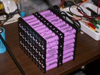
I started by laying out half the pack and started welding. Each cell has a series connection to the next. I used only one parallel connection. You could use two, but these normally don't carry much current and don't need to be very large.
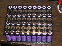
I did the second half, then brought the two halves together. The halves aren't interlocked, so the nickel tabs need to be a little longer.
View attachment 10
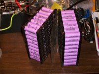
Once those tabs were welded, the pack gets folded in the middle with a sheet of 1/16" polycarbonate between them. The cell holders keep the tabs apart, but I wanted an extra layer of protection in the event of a crash. This also stiffens the pack.
View attachment 8
Test fitting the pack into the housing:
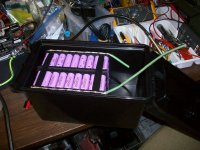
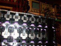
At the ends of the pack, I used some 8ga copper wire soldered to the tabs for the parallel connection. I thought about using equal length smaller wires bundled into a single one, but this looks cleaner and the heavy copper should provide even enough current distribution. Some combination of these approaches might be more optimal.
The BMS unit is a modified D126 from Bestech Power. Originally was rated at 20A discharge. I replaced the FETs and added a heat sink. Also the shunt resistors were modified and copper added to bring the rating up to 60A. I don't plan on running at 60A, but I don't want the thing tripping on me at 50A. The heat sink on the BMS was mounted to another piece of aluminum with insulated hardware. This plate goes directly against the wall of the box, so any heat generated will have someplace to go. So far, I haven't detected any heating at all.
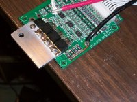
I mounted the BMS so I would have easy access to the balance wire connectors on top. This makes measuring cell voltages easy by back probing where the wires go into the connector. All the balance wires go to the parallel connections on the cells. In this arrangement they all come of the same side of the pack and reach nicely.
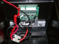
I placed sheets of polycarbonate on the outside faces of the pack and used gigantic zip-ties to anchor the pack to the bottom of the can. I used a Dremel tool to make slots for the ties on the bottom.
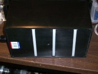
These ties are really strong. I left them a little long to make taking them apart and reused possible. In the event of an impact, the case acts like a helmet for the pack, which is tightly bundled up by the zip ties.
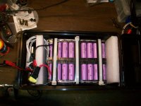
The yellow thing is a 60A fuse. The BMS also has short circuit protection, but I trust a fuse more. Also visible is the charging connector. This is keyed differently than the discharge connector in case I get stupid someday.
The polyethylene foam blocks prevent contact between the pack connections and the BMS if things shift. I threw some on the other end for more protection. In hindsight, I think I could have fit 12p cells with clearance. 9p is OK, and weighs less.
Here's the finished pack: Final weight: 16.5 lbs. (7.5kg). Nominal 54v, 22Ahr.
View attachment 1
Mounted on the bike:
On the first test ride, I ran it mostly full throttle for the whole ride to test for heating. I'm using the stock A2B controller, which has a current limit around 22A. At 52v, it goes about 26mph on flat ground. After running it as hard as I could for about 30 min, I stopped and checked for heat. The cells were mildly warm. The BMS was cold. I ran it hard on the return trip and just as I was in front of my house, the controller cut out. Lights OK, voltage OK, no power. I figure I tripped some kind of thermal protection in the controller. Eventually it reset itself and started working normally again. Time for the external controller...
Anyway, the cells and BMS worked well. After a few charge cycles, it should improve a little. On the test trip I used 9Ahr over a distance of 17.5 miles. If I rode at 20mph, I figure it should have a range of around 50 miles. I plan to upgrade the controller to around 40-50A and I think it will work OK.
On to the 18650s...
I got a great deal on some test cells from member Jim Hagerty, along with a bunch of the little black interlocking cell holders. These are available on eBay or Aliexpress. I also got a JP Spot welder from riba2233 https://endless-sphere.com/forums/viewtopic.php?f=31&t=68865. The spot welder is a dream come true for building 18650 packs.
Based on rough measurements and materials on hand, I decided on a 14s9p configuration. The battery holders go together easily and have recesses for the nickel strips. You could probably do just as well to use nickel sheet and a different style of holder that doesn't cover the ends, but these seemed to work well for me.
I decided on a plastic .50cal ammo can made by MTM. These go for around $20. It has a gasket on the lid, nice latches, a carrying handle, won't rattle and are reasonably strong and lightweight. It should protect fine against rain. I saw these in green and orange as well as black. Black matches my bike, so that's what I got. I wanted something with a handle since I take the pack off every time I ride and bring it in the garage for charging. To fit the can, I needed to use two rows side by side.

I started by laying out half the pack and started welding. Each cell has a series connection to the next. I used only one parallel connection. You could use two, but these normally don't carry much current and don't need to be very large.

I did the second half, then brought the two halves together. The halves aren't interlocked, so the nickel tabs need to be a little longer.
View attachment 10
Once those tabs were welded, the pack gets folded in the middle with a sheet of 1/16" polycarbonate between them. The cell holders keep the tabs apart, but I wanted an extra layer of protection in the event of a crash. This also stiffens the pack.

View attachment 8
Test fitting the pack into the housing:

At the ends of the pack, I used some 8ga copper wire soldered to the tabs for the parallel connection. I thought about using equal length smaller wires bundled into a single one, but this looks cleaner and the heavy copper should provide even enough current distribution. Some combination of these approaches might be more optimal.

The BMS unit is a modified D126 from Bestech Power. Originally was rated at 20A discharge. I replaced the FETs and added a heat sink. Also the shunt resistors were modified and copper added to bring the rating up to 60A. I don't plan on running at 60A, but I don't want the thing tripping on me at 50A. The heat sink on the BMS was mounted to another piece of aluminum with insulated hardware. This plate goes directly against the wall of the box, so any heat generated will have someplace to go. So far, I haven't detected any heating at all.

I mounted the BMS so I would have easy access to the balance wire connectors on top. This makes measuring cell voltages easy by back probing where the wires go into the connector. All the balance wires go to the parallel connections on the cells. In this arrangement they all come of the same side of the pack and reach nicely.

I placed sheets of polycarbonate on the outside faces of the pack and used gigantic zip-ties to anchor the pack to the bottom of the can. I used a Dremel tool to make slots for the ties on the bottom.

These ties are really strong. I left them a little long to make taking them apart and reused possible. In the event of an impact, the case acts like a helmet for the pack, which is tightly bundled up by the zip ties.

The yellow thing is a 60A fuse. The BMS also has short circuit protection, but I trust a fuse more. Also visible is the charging connector. This is keyed differently than the discharge connector in case I get stupid someday.
The polyethylene foam blocks prevent contact between the pack connections and the BMS if things shift. I threw some on the other end for more protection. In hindsight, I think I could have fit 12p cells with clearance. 9p is OK, and weighs less.
Here's the finished pack: Final weight: 16.5 lbs. (7.5kg). Nominal 54v, 22Ahr.
View attachment 1
Mounted on the bike:
On the first test ride, I ran it mostly full throttle for the whole ride to test for heating. I'm using the stock A2B controller, which has a current limit around 22A. At 52v, it goes about 26mph on flat ground. After running it as hard as I could for about 30 min, I stopped and checked for heat. The cells were mildly warm. The BMS was cold. I ran it hard on the return trip and just as I was in front of my house, the controller cut out. Lights OK, voltage OK, no power. I figure I tripped some kind of thermal protection in the controller. Eventually it reset itself and started working normally again. Time for the external controller...
Anyway, the cells and BMS worked well. After a few charge cycles, it should improve a little. On the test trip I used 9Ahr over a distance of 17.5 miles. If I rode at 20mph, I figure it should have a range of around 50 miles. I plan to upgrade the controller to around 40-50A and I think it will work OK.

