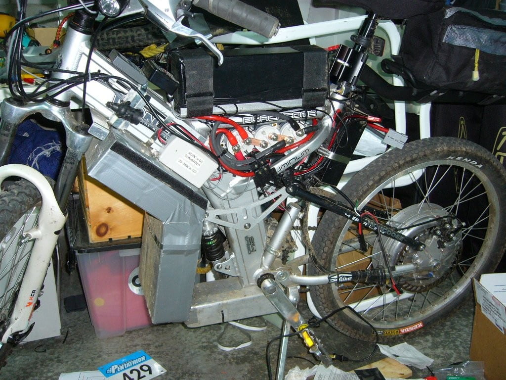
Ac to dc inverter.....need 12-14v?

steveo

100 kW
Joined
Oct 6, 2007
Messages
1,786
Location
Woodbridge, Ontario
Hey Everyone,

I have been trying to find a dc to dc inverter for my 144v dc bike to 12v-14v dc ... and i was missing the obvious ...

i could use a switching 115v-250v ac to 12v dc power adapter... (a good one to use is for laptop!)

i just think everyone should know this .. i don't know how i missed trying this easy ... lol

a pic of docs inverter... (stole your pic doc :p)

file.php


-steveo
 
I purchased a universal 15-24V laptop power supply off of eBay and it worked as a DC-DC converter with my 48V battery for a few minutes until it got very hot and died. Maybe a fixed single-voltage power supply would fare better since the output seemed stable at the lower voltages then started dropping (just before it went poof) when I selected the higher output voltages.

-R
 
For lower current use I have used cellphone chargers and laptop supplies on my 36V pack as a series booster to run my CFL lighting (since it wouldn't start properly on just the pack voltage), and they run cool enough. But I expect that they'd not run so well at higher current output demands with a lower-than-expected input voltage. At the 144VDC, I'm sure they'd be fine. At 48VDC, less than half of the designed input voltage, they're going to need a lot more current input to get the same power output, and that might be fatal to some of the electronics inside, depending on the designs. Especially if it does so in a way that causes extra heat, which will kill the sealed-up bricks quickly.

The only real worry on any voltage I would always have is that most of them will have rectifier bridges designed to carry half the total input power required on each half of the bridge, but when used on DC input they're only going to be able to get that power thru one of those halves, whcih might not be capable of carrying it. Simply soldering the input wires to the + and - of the bridge instead of the AC ~ ~ inputs would fix that.
 
AW,

I assume there must be extra components between the bridge and AC receptacles. Should you just look for the diode/BR closest to the input? I smoked a 12V 1A ps the other day by just hooking up to the AC inputs. It was just an old 750MB Iomega Zip Drive ps, so no big deal. Actually got another one I'll try your suggestion on. :wink: Thanks!

amberwolf said:
For lower current use I have used cellphone chargers and laptop supplies on my 36V pack as a series booster to run my CFL lighting (since it wouldn't start properly on just the pack voltage), and they run cool enough. But I expect that they'd not run so well at higher current output demands with a lower-than-expected input voltage. At the 144VDC, I'm sure they'd be fine. At 48VDC, less than half of the designed input voltage, they're going to need a lot more current input to get the same power output, and that might be fatal to some of the electronics inside, depending on the designs. Especially if it does so in a way that causes extra heat, which will kill the sealed-up bricks quickly.

The only real worry on any voltage I would always have is that most of them will have rectifier bridges designed to carry half the total input power required on each half of the bridge, but when used on DC input they're only going to be able to get that power thru one of those halves, whcih might not be capable of carrying it. Simply soldering the input wires to the + and - of the bridge instead of the AC ~ ~ inputs would fix that.
 
number1cruncher said:
I assume there must be extra components between the bridge and AC receptacles. Should you just look for the diode/BR closest to the input? I smoked a 12V 1A ps the other day by just hooking up to the AC inputs. It was just an old 750MB Iomega Zip Drive ps, so no big deal. Actually got another one I'll try your suggestion on. :wink: Thanks!

First, make sure it is not a transformer-based wallwart. If what you see inside is a bridge, a cap, a single large transformer, then you can't use that kind on DC. It *will* smoke when you hook up DC to it if the windings aren't capable of the current load, because it will just flow current steadily thru it like a long piece of wire. The transformer comes first electrically, so right off the AC input prongs.

If it's a switched supply (usable for DC-DC operation), it will have first a bridge, then caps, then some switching electronics like transistor, MOSFET, or IGBT, then small transformer, then some more electronics like TO220-style diode packs/etc, more caps, sometimes another transformer or inductor that looks like one, etc. Often lots of little parts around it and maybe an IC for control, sometimes more than one.

If the SMPS type uses a fullwave bridge (the only type you'd have to worry about) there will either be a bridge module or four diodes on the board before the main input cap(s) but after the AC input wires. They will be wired up so two have their striped ends connected, the other two have their non-striped ends connected, and the two sets will be connected at their opposing ends stripe-to-non-stripe. You just need to move the input to the points where the two stripes connect (for -) and where the two non-stripes connect (for +).

If it's a bridge module, it'll have four pins, two with ~ marks and two with + / -. Just hook in your DC input to the + / -.


If there is only two input diodes, it's a half-bridge, and will only pass current one-way anyway, so doesn't matter if you bypass it or not. The only advantage to bypassing it is that you get about 1.4V less drop on the input, thus that much more ability to put out power from the adapter as a whole.
 
Back
Top