Doctorbass
100 GW
Adaptto diy 70A charging coil
not an easy project finally!! :lol:
It require a parallel capacitor and a serie inductor between the power supply and the controller charging connections. I already have the right quality capacitor but the inductor is something a little bit more complicated….
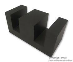
After i did many test with various inductor that I modified and various core that I have wound to meet the suggested inductance value, I finally decided to order the real recommended core “E” (The Epcos E 70/33/32) and to wound my own inductance.
According to the Adaptto manual the recommended inductance shall be between 15 to 30uH.
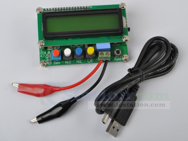
Unfortunately my Meterman XR37 DVM multimeter can normally measure inductance but it had a poor result at such low inductance value so I have ordered one specific inductance meter on ebay for about 25$ that work like a charm and is very accurate for low inductance. In fact it also measure the capacitance very well!
So I have measured many high current inductors that i already had from various salvaged power supply. And in some cases I removed some turn to get between 15-30uH.
Finally what happened:
All of them worked and was able to boost the current to 91-92V for charging but their core was becoming VERY hot !!! and would have melted the wires if I would have not cut the power in time!. That is something strange…in fact the wire temp was OK but the core was very hot!.. So I suspected that the core was saturating and was probably too small for that amount of power. I was testing from 250 to 1200W with meanwell RSP 1000-48. I have tried many combinaisons of toroidal and E shape core with multiple parallel small strands from switching power supply I salvaged without positive success.
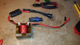
Yesterday I received the Epcos big ”E” core and add a air gap between both E core parts to lower the inductance as it is recommended ( about 1.5 to 2mm) and also installed 12 gauge turnigy silicon wire for about 10 turns and I got around about 35uH. Then connected it to the power supply and capacitor and controller input and I was able to push the power up to 1100W and the big E core remained ice cold !!! success!!
So I can conclude that the core volume and cross sectional area is very important in regard of the power amount and also frequency that is used. In the case of the Max-E with lastest firmware Rc9b it’s 18khz.
Today at the lunch I have discharged my 22s battery to 50% soc and wanted to push more power to it with the new working coil but this time strangely the 100v 680uF capacitor was buzzing seriously and heating… that never happened before…. And laso the current the power supply was giving was higher than the charge current measured by the controller… finally it heated so much that the negative leg melted !
Next plan are to investigate why with lower SOC battery the capacitor was having a problem and I was not able to push power to the battery.
Then I will replace the turnigy 12 gauge wire by a parallel bundle of 22 gauge wires. I will use probably 36 to 40 strands in parallel but isolated by varnish 9 only soldered at their end)
Apparently there is also another parameter about inductor that some people are using witch is a different way to take all the strands together. It,s called Litz wire witch consist of twisting multiple pair together and then to twist all these pair together but in opposite twisting direction… this apparently reduce the skin effect. Witch is something I did not tested yet…
Well inductor are not as easy as I expected as well. Some of you would have probably preferred to order directly the full harness coil assembled with the caps and connector and plug and play!
But I want to understand how it work and I already have some parts so why not!
I have learned a lot about inductance here: https://www.youtube.com/watch?v=3b8Wol-X4tE
LCR meter from ebay:
http://www.ebay.com/itm/High-Precis...2ba26&pid=100011&rk=2&rkt=10&sd=221630445296
The Epcos ferrite that I bought ( same as Adaptto big 70A E coil)
http://www.kosmodrom.com.ua/pdf/e_70_33_32.pdf
Litz wire thread:
http://endless-sphere.com/forums/viewtopic.php?f=2&t=66615&p=1001898&hilit=litz+wire#p1001898
some advices form andreym:
Electrotransport.ru thread about that:
http://electrotransport.ru/ussr/index.php?topic=25546.0
Inductor charging through the controller on Electrotransport.ru
http://www.microsofttranslator.com/...ssr/index.php?topic=18930.msg327156#msg327156
Doc
not an easy project finally!! :lol:
It require a parallel capacitor and a serie inductor between the power supply and the controller charging connections. I already have the right quality capacitor but the inductor is something a little bit more complicated….
After i did many test with various inductor that I modified and various core that I have wound to meet the suggested inductance value, I finally decided to order the real recommended core “E” (The Epcos E 70/33/32) and to wound my own inductance.
According to the Adaptto manual the recommended inductance shall be between 15 to 30uH.
Unfortunately my Meterman XR37 DVM multimeter can normally measure inductance but it had a poor result at such low inductance value so I have ordered one specific inductance meter on ebay for about 25$ that work like a charm and is very accurate for low inductance. In fact it also measure the capacitance very well!
So I have measured many high current inductors that i already had from various salvaged power supply. And in some cases I removed some turn to get between 15-30uH.
Finally what happened:
All of them worked and was able to boost the current to 91-92V for charging but their core was becoming VERY hot !!! and would have melted the wires if I would have not cut the power in time!. That is something strange…in fact the wire temp was OK but the core was very hot!.. So I suspected that the core was saturating and was probably too small for that amount of power. I was testing from 250 to 1200W with meanwell RSP 1000-48. I have tried many combinaisons of toroidal and E shape core with multiple parallel small strands from switching power supply I salvaged without positive success.
Yesterday I received the Epcos big ”E” core and add a air gap between both E core parts to lower the inductance as it is recommended ( about 1.5 to 2mm) and also installed 12 gauge turnigy silicon wire for about 10 turns and I got around about 35uH. Then connected it to the power supply and capacitor and controller input and I was able to push the power up to 1100W and the big E core remained ice cold !!! success!!
So I can conclude that the core volume and cross sectional area is very important in regard of the power amount and also frequency that is used. In the case of the Max-E with lastest firmware Rc9b it’s 18khz.
Today at the lunch I have discharged my 22s battery to 50% soc and wanted to push more power to it with the new working coil but this time strangely the 100v 680uF capacitor was buzzing seriously and heating… that never happened before…. And laso the current the power supply was giving was higher than the charge current measured by the controller… finally it heated so much that the negative leg melted !
Next plan are to investigate why with lower SOC battery the capacitor was having a problem and I was not able to push power to the battery.
Then I will replace the turnigy 12 gauge wire by a parallel bundle of 22 gauge wires. I will use probably 36 to 40 strands in parallel but isolated by varnish 9 only soldered at their end)
Apparently there is also another parameter about inductor that some people are using witch is a different way to take all the strands together. It,s called Litz wire witch consist of twisting multiple pair together and then to twist all these pair together but in opposite twisting direction… this apparently reduce the skin effect. Witch is something I did not tested yet…
Well inductor are not as easy as I expected as well. Some of you would have probably preferred to order directly the full harness coil assembled with the caps and connector and plug and play!
But I want to understand how it work and I already have some parts so why not!
I have learned a lot about inductance here: https://www.youtube.com/watch?v=3b8Wol-X4tE
LCR meter from ebay:
http://www.ebay.com/itm/High-Precis...2ba26&pid=100011&rk=2&rkt=10&sd=221630445296
The Epcos ferrite that I bought ( same as Adaptto big 70A E coil)
http://www.kosmodrom.com.ua/pdf/e_70_33_32.pdf
Litz wire thread:
http://endless-sphere.com/forums/viewtopic.php?f=2&t=66615&p=1001898&hilit=litz+wire#p1001898
some advices form andreym:
more inductance you have = easier for controller, But I`d suggest to fill maximum by adding strands in parallel, and you can add more air gap between the to E core parts, this will decrease the inductance as well.
Electrotransport.ru thread about that:
http://electrotransport.ru/ussr/index.php?topic=25546.0
Inductor charging through the controller on Electrotransport.ru
http://www.microsofttranslator.com/...ssr/index.php?topic=18930.msg327156#msg327156
Doc
")