bradleyk
10 mW
Hey Guys.
Aiming to build a motor controller over the summer(Aus) for an electric car. Current battery is 24s2p, once everything is up and running I will be aiming for 30s(120v nominal) or so. Planning an 18 fet controller. 12-15Kw Continuous, 20-25Kw peak for starters I believe I should be able to get 20Kw-25Kw continuous 40Kw peak? out of an 18 fet.
As I am designing for a car, the australian guideline require traction battery to be completely isolated from everything. So this will be driven from the can bus via isolated transceivers.
There will be a main 24v bus for the drivers regulated down from 150v, 8v for 5v regulators one for all on board, with the other for all wiring that will leave the controller.
As I am still young and naive please forgive any errors.
But I have a few Questions.
Mosfet's
These IRFP4568 seem to be the weapon of choice in the forums. just double checking these are still the goto for 150v
Zombies motor driver.
[strike]I ordered some of his pcb's, But I am going over the schematic and I believe there is an error.
Wouldn't the connection into pin 7 mean the optocoupler will always be on? essentially shorting +5 through the base of the transistor?[/strike]
Connectors
Looking at Molex KK 254 series for the main battery.
For the motor driver to work it needs to monitor the motor voltages on the pcb. trying to decide on the required connectors to maintain the safe distance. I believe that would be about 1.5mm for 150v, just want to confirm the KK 254 series won't go bang, I suspect I should add conformal coating over the HV stage for safety.
The KK series is rated for 24 AWG, that should be strong enough to resist breakages from vibrations? lots of zip ties?
Switch mode supply
I am using something similar to lebowski's design as finding an IC for 150v is proving difficult. I cam across this FDC2515 how does a SOT-6 maintain the required clearance for 150v i'm getting around 0.26mm clearance between pins.
The aim of this project is a learning curve. I would Like to be able to drive to the shops and back. If I can make it to the end of the street with V1 I would consider it a success.
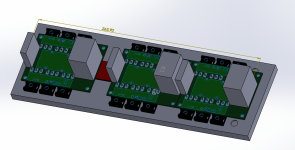
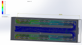
Curent progress

Aiming to build a motor controller over the summer(Aus) for an electric car. Current battery is 24s2p, once everything is up and running I will be aiming for 30s(120v nominal) or so. Planning an 18 fet controller. 12-15Kw Continuous, 20-25Kw peak for starters I believe I should be able to get 20Kw-25Kw continuous 40Kw peak? out of an 18 fet.
As I am designing for a car, the australian guideline require traction battery to be completely isolated from everything. So this will be driven from the can bus via isolated transceivers.
There will be a main 24v bus for the drivers regulated down from 150v, 8v for 5v regulators one for all on board, with the other for all wiring that will leave the controller.
As I am still young and naive please forgive any errors.
But I have a few Questions.
Mosfet's
These IRFP4568 seem to be the weapon of choice in the forums. just double checking these are still the goto for 150v
Zombies motor driver.
[strike]I ordered some of his pcb's, But I am going over the schematic and I believe there is an error.
Wouldn't the connection into pin 7 mean the optocoupler will always be on? essentially shorting +5 through the base of the transistor?[/strike]
Connectors
Looking at Molex KK 254 series for the main battery.
For the motor driver to work it needs to monitor the motor voltages on the pcb. trying to decide on the required connectors to maintain the safe distance. I believe that would be about 1.5mm for 150v, just want to confirm the KK 254 series won't go bang, I suspect I should add conformal coating over the HV stage for safety.
The KK series is rated for 24 AWG, that should be strong enough to resist breakages from vibrations? lots of zip ties?
Switch mode supply
I am using something similar to lebowski's design as finding an IC for 150v is proving difficult. I cam across this FDC2515 how does a SOT-6 maintain the required clearance for 150v i'm getting around 0.26mm clearance between pins.
The aim of this project is a learning curve. I would Like to be able to drive to the shops and back. If I can make it to the end of the street with V1 I would consider it a success.
Curent progress