• Hello ES! We could use some help to get us past the finish line on building the new knowledgebase for the forum.
    Can you donate? Please see our fundraising page. Thank you!

New 100A FOC controller project

Mihai_F

Established
Joined
Oct 11, 2021
Messages
234
Hy guys,
As mentioned in my post New Custom Motor Project for Solar Car
Here i'l describe the FOC controller. It's design begun a year ago, when i started looking into making an single board all smd FOC esc and also started developing the FOC code for STM32 uC-s. A verry big inspiration for code came from MESC code, big thanks' to David. Also the hardware got a bit inspired from MESC board in regard with the close placement of the power FET's.
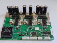
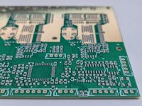
The design is nothing new under the sun, its rating is 100A phase amps, it can be in 60V 80V 100V rating depending witch FDBL86xxx (12 fet design) series FET's are used, dc-dc power brick for HV step down, 150A hall current sensors from allegro (ACS72981), F446 uC, RS232 UART, CAN, ect... At 60V rating the fet-s have 1.1mohm rdson so 2 in parallel will be super low dissipation, but at 100V rating fet-s have 5mohm rdson with 2 in parallel there is still quite some dissipation, so that is why 12 fets, for continuous use and not over heat. Gnd bus power traces have copper plates on top for current reinforcement, positive bus is 2 big fat wide planes on 2 layers. Board is 4 layers, 2oz outers , 0.5oz inners, it sits on a sillpad on its entire surface and then bolted to the heatsink (150x100x25mm has machined surface to clear pins of the THT devices), and aluminum casing, as usual for me :D .
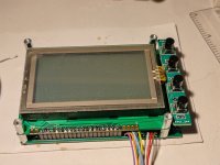
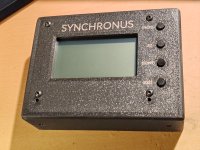
The display is the same setup used on my plane, went with 3D printed case this time... , the code needed some rearrangement of the graphics to show speed and land based vehicle parameters.
I made 2 at once, on 60V rated for my drift trike build and one 100V rated for the solar car. Unfortunately my FOC SW was not mature enough to use in the solar car on the race day, so we used a backup controller (kelly).
I'l come later with measurement plots on the scope.
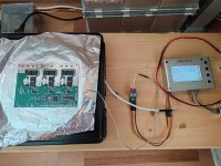
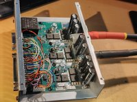
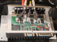
Here are some photos of the boards,
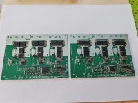
IMG_20240905_104029.jpg
IMG_20240905_165935.jpg
IMG_20240905_170838.jpg
IMG_20240906_114616.jpg
IMG_20240915_221000.jpg
IMG_20240916_235258.jpg
IMG_20240915_013050.jpg
IMG_20240915_221752.jpg
 
i'm back with measurements,
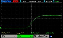
I did the double pulse test, supply 40V inductor 24uH, first did 97A then 127A, then went full hog with 148A and 183A twice, and the software overcurrent protection kicked in and stopped the second pulse. (unfortunately SW protection is not like HW desat protection in my 300A controller for plane, but still cool tough) Then repeated the 127A DPT and analyzed closely the data, it seems fine, no ringing just a 5v overshoot, the shots are inverted, the measurement is for high side Vds.
HS Vds turn on (inverted)
dso_01_01_06_07_57.jpg
HS Vds turn off (inverted)
dso_01_01_06_09_18.jpg
HS Vds DPT second pulse (inverted)dso_01_01_06_05_04.jpg
HS Vds DPT all pulses (inverted), see the supply sagging almost 5v (limited current supply)
dso_01_01_06_03_31.jpg
LS Vgs yellow, Vds green, during PWM-ing about 60A (phase Amps) in a 12uH inductor for one second
dso_01_01_00_40_05.jpg
dso_01_01_00_42_02.jpg
Here is the confirmation of the current 127A logged by the uC, (current was logged just like in MESC code for DPT)
blue beginning of the first pulse 89A
red end of the first pulse 127A
green beginning of the second pulse 124A
second red end of the second pulse 89A
light blue freewill current after the second pulse 78A
D_P_T_5_127A longer second pulse.png
And the 183A one
D_P_T_1_183A_1.png
So far i'm pleased with the results of this hardware.
Next, il put it on my drift trike and abuse the heck out of it, and have some fun.
 
Very nice results. I also use Psof8 mosfets in a few projects and I am very satisfied.

Can you give information about double pulse test? How long do you program the pulse? And how fast was the current control response?
 
Nice. This looks super similar to the first VESC I ever made in layout. You can easily push that to 400A for a few seconds. Unless you accidentally messed something else up on it.

Like the choice of MCU.
 
Are you using the box as a ground? I recommend against that. Arcs to the case/inside the motor from battery and phase wires are very very hard to extinguish and irritatingly common. Don't ground the negative of the battery.
 
Very nice results. I also use Psof8 mosfets in a few projects and I am very satisfied.

Can you give information about double pulse test? How long do you program the pulse? And how fast was the current control response?
You need 2 pulses, one long in order to raise the current, and the second to switch the DUT on/off in that current .For 127A in 24uH inductor at 40V the pulse was ~130us. Over current detect is SW, in 44us intervals , pwm triggering injected ADC for current.
 
Are you using the box as a ground? I recommend against that. Arcs to the case/inside the motor from battery and phase wires are very very hard to extinguish and irritatingly common. Don't ground the negative of the battery.
yep, the box is grounded to B- , mostly for EMI shielding, although the heatsink is isolated from vehicle chassis ground, the electric propulsion has its own ground witch is isolated from vehicle ground. I know and understand what you say about grounding the heatsink/chassis to B-, one plan for future is to have isolated the HV B- from LV GND, and then only LV will be grounded to chassis. In electric vehicles (cars) there is a voltage divider connected to B+ and B- and the middle point is connected to chassis gnd, the ECU constantly measures that with respect to B+ and B- and if it deviates from what it should be (half HVbatt) it throws isolation error and disconnects the main contactor solenoid, to avoid nasty problems.
 
yep, the box is grounded to B- , mostly for EMI shielding, although the heatsink is isolated from vehicle chassis ground, the electric propulsion has its own ground witch is isolated from vehicle ground. I know and understand what you say about grounding the heatsink/chassis to B-, one plan for future is to have isolated the HV B- from LV GND, and then only LV will be grounded to chassis. In electric vehicles (cars) there is a voltage divider connected to B+ and B- and the middle point is connected to chassis gnd, the ECU constantly measures that with respect to B+ and B- and if it deviates from what it should be (half HVbatt) it throws isolation error and disconnects the main contactor solenoid, to avoid nasty problems.
Good that at least the box is isolated from the chassis. Personally I'd never rank EMI concerns above shorting concerns. Both are of course critical for a commercial product but if you're making one offs for fun... Well flames outrank hypothetical gremlins in any circumstance i can think of. What people blame on EMI is very very rarely actually EMI, it's usually crappy ground connections or ground loops or something like that. It's standard practice in most software departments to blame EMI for memory leaks, floating pins firing interrupts, unterminated reset lines, divide by zeros, delay until, while (1){}...
 
... It's standard practice in most software departments to blame EMI for memory leaks, floating pins firing interrupts, unterminated reset lines, divide by zeros, delay until, while (1){}...
yeah that is a good one :D , heard of that

EMI topic for me is to keep it inside and not get out the "box", to protect the radio reception, comms....

There was a team at solar car racing that used some vesc based controller, they had big trouble tuning it to the motor, and it was running verry rough, it sounded like it was working on steam (not joking) , and every lap when they passed by us at stands our radio was buzzing loud, so EMI stuf....
 
Last edited:
I'm back with updates, i worked a lot on SW, but now it runs really great.
still sensored start up and then switches to sensorless FOC.
new features added it has field weakening and regenerative braking, and the UI for the display is updated with may features.
phase current was set at 80A so that bus current is self limited to about 65A (battery limit) (edited typo)
with field weakening 20A the speed increases from 51 to 61Km/h no load, to be tested on road
so far i tested regen up to 3A (batt max charge is 5A), seems stable.
here is a video "testing" the controller, it rips
 
Last edited:
Went for out for more testing with drift trike.

The phase amps set at 100A, power limiter set at 3,4kw. Now it pulls more aggressive, it can do burnout right after startup with me (heavy load) on it, after 30min of intermittent "aggression"(say 50% duty) the controller got up to 46degC max (22degC ambient).

Regen set at 10A (20A phase), now it can be felt braking and also felt/seen in the battery charging (voltage rising). Right now i'm thinking of a regen power limiter so i can have constant regen current regardless of motor speed, at least down to certain low speed, so i'l implement it, test it, and repot back.

Motor(MY1020) seems fine so far, it gets warm (say 40 deg C), i'm a bit conservative with continuous power no it, so it does not get overheated and demagnetize rotor, i have to mount the temp sensor on it, so the controller knows when to let off the "abuse", and the batt temp sensor also, these 2 are my main concerns as regard temps.
 
Update, finished all the wiring (12v and 60v)circuits, and also temp sensors to motor and batt. Now i have regen activating with brake levers. Went for testing (driftrike) with 20A field weakenig and 110A phase amps, and 12A regen un bus, 24A on phase. Now is really agresive, max speed on level ground was 52km/h, max power 3,8kw, ambient was 28degC. Still to implement constant regen current. Still to test more field weakenig current since at 52km/h the power is 2kw, so there is still room to go more. Will report back. 1000040169.jpg
 
I'm back with some update, i performed an "abusive test" on the controller, at first it happened involuntarily and then i did it deliberately, and that is battery disconnect at high power levels, (4kw, 110A phase). All went fine nothing damaged, did the test several times. Unfortunately did not have any chase to measure it on scope, so basically relied on the results from double pulse test i did in the past on it, and hoped it will be fine here also, and went for it. This was needed mostly because some batteries have it's own BMS inside and if it decides to cutoff power for its own reasons, the controller must survive just fine. Now in normal/correct settings and use, that will only happen if a cell/s goes below 3v.
That said, i'm working now on installing my own BMS that will stay on the battery side/inside and communicate via UART (RS232) with the controller, so it can know the cells voltages and also do balance constantly.
The controller that i have on my aircraft (300A 18FETs THT ) has a BMS inside and that only measures the cells, that works kind of ok, but has many limitations due to long sense wires, hence the reason this present controller has the BMS moved on the batt side and eliminating those problems and can do balance also.
The charger that charge this batteries does have BMS constant balance feature and a port to sense up to 22cells, so that might be also exchanged for the inside batt BMS witch communicates on RS232 with charger also, and eliminating long sense wires here also.
All in all, long sense wires for cells are not desirable, so a BMS on battery side is the best option, but still i'm doing it such way that the cells sense cable to be able to be disconnected from the BMS when battery is not in use, mainly because in 20 years of lithium batt usage all went fine wile having nothing connected to them when they ware not is use , basically i'm not comfortable having a lithium battery with some electronic device permanently connected do it, and be stored inhouse.... i'f i would have a fire proof concrete underground bunker, then it will be another story :mrgreen: .
 
Since I don't know enough engineering to figure out the details myself, could you give a summary of the general idea of what in this controller helps prevent the kinds of failures that can occur upon battery disconnect during controller operation?

And do these also mitigate similar failures caused when regen braking feedback to the battery is interrupted by a battery disconnect?
 
Since I don't know enough engineering to figure out the details myself, could you give a summary of the general idea of what in this controller helps prevent the kinds of failures that can occur upon battery disconnect during controller operation?

And do these also mitigate similar failures caused when regen braking feedback to the battery is interrupted by a battery disconnect?
First, the knowledge that i got in building controllers, was learned mostly on this forum, so thanks and respect to users that guided me.
So first i'm going to describe in a simplified way the principles of the controller "switching", witch is kind of complex subject.
We consider for simplicity one third of the 6 bridge, so we have the mosfets high side and low side, the active switching parts witch have a rating called Vds, witch we do not ever want to exceed, in my case 80V, usually best practice is to have maximum battery voltage 70% of that Vds, so that the rest of 30% is headroom for safety.
Now in parallel with these 2 mosfets we have the ceramic capacitors with some small parasitic inductance in between, the DC link electrolytic capacitors with even more parasitic inductance and the battery with the inductance of the cable from batt to cont. Battery in it's own "acts" as a verry big capacitor for the controller, and because we have those battery cables (inductance) (even if they are short), we need those DC Link caps to "reduce the effect" of the inductance of cables hence "DC link", it links the "DC" of the batt to the cont .
So all that high current (100A) switching thru all that "chain" mentioned above, will create an voltage overshoot on mosfets Vds, due to all that parasitic inductance, every time the mosfet turns off high current, the parasitic inductance gives a voltage "kickback" witch is absorbed(snubbed) mostly by the ceramic caps and some by the DC link caps.
One key element to achieve the lowest Vds overshoot due to switching, is to have the smallest loop area in the switching loop/node (marked with red on the photo) and this is what keeps the controller/ mosfets alive.
And while "motoring" (running the motor at high power) high frequency content currents "go thru" the ceramic capacitors, lower frequency content currents "go thru" the DC Link caps, and "continuous -ish" currents thru battery.
Now, the problem with battery disconnect under load while "motoring", is if there is big Vds overshoot in normal operation, and the extra overshoot because all the current coming from battery thru cables (inductane again), then the ceramic caps and DC Link caps can not hold all the overshoot in Vds limits, after that big capacitance of the battery is disconnected.
So in my controller (nothing new under the sun, there are many similar on this forum) the layout was done in such way to minimize the loop area in the switching node, plus using TOLL (leg less) package mosfets witch have verry low parasitic inductance compared to THT (with legs) mosfets , and this creates a clean switching with verry low overshoot on Vds, see post #2.
sw_block.jpgsw_loop.jpg

Now regenerative braking batt disconnect is another "topic" that gets it's effect superimposed over the effect mentioned above. Regen in simple terms uses the mechanical energy from motor to "create" a voltage higher that battery voltage in order to charge it. The higher the voltage the higher the regen (charging) current and the braking force.
The controller "acts as a boost converter" in regen, and the battery is the "load". So if that battery "load" gets disconnected during high regen currents, all that current does not have where to go any more, and if the controller does not react in useful time, it will "boost" the voltage over the Vds limit, then smoke and sparks come out of mosfets.
Usually software Vbus monitoring is nowhere near fast enough to protect the mosfets, so a complex hardware solution is needed to react in verry fast manner under 0,5us.
My controller was only tested up to about (very shot time 1sec) 2A regen current and batt disconnect and Vbus went up verry close Vds, because software can not react faster than 44us (PWM period), so will not survive battery disconnect during high regenerative currents (12A for ex.).
Hope that the explanations was simple enough to be understood, this topic has a lot of details and complex working principle in all its details.
 
Back with some progress in a different direction. So this type of controller is used on my trike for 3, and that "rig" has bicycle changing gears, this means that the vehicle speed can not be determined from motor RPM if it is not spinning and vehicle is moving/ coasting, plus not knowing the gear selection. The solution is a wheel speed pick up sensor, like in bike speedometer.
The controller has 4 auxiliary input channels (unused in this application) for whatever purpose, so i will connect a Reed relay/switch to one of those inputs, and 2 magnets on the wheel spokes for better speed resolution at low speeds, did some bench testing and made the calculation algorithm, nothing fancy, just a timer and some math. Did some tests, it woks but i could be better, reed sensor could be more sensitive, so that magnet could be further apart from reed sensor than 3-5mm, but yeah...
My question is what type of sensor have any of you used for bike wheel speed pick up, and if there is a better way than Reed relay/switch
 
My question is what type of sensor have any of you used for bike wheel speed pick up, and if there is a better way than Reed relay/switch

Simply Hall effect sensor - Wikipedia


There's plenty of sensors made for bikes(china) that would be plug&play, (as long as you come up
with or replace the necessary 3pin connector) for any mcu able to handle 5V peripherals.
 
Last edited:
Simply Hall effect sensor - Wikipedia


There's plenty of sensors made for bikes(china) that would be plug&play, (as long as you come up
with or replace the necessary 3pin connector) for any mcu able to handle 5V peripherals.
yeah, that was may thought initially, although i opened in the past bike sensors and they ware done with Reed sensor, only 2 pins, and did not see/ try other higher quality ones that use halls. So i have halls, the bipolar ones, change outputs depending on N/S pole, but in the absence they stay at what ever was left before, so if you only show it a single pole, say N, it will not change its state, so one solution is 2 magnets one N one S, but then this solution is "active"(hall) in nature and a bit to complex. So yeah still looking for something like automotive ABS passive sensors, the active ones use Hall.
 
So i have halls, the bipolar ones, change outputs depending on N/S pole, but in the absence they stay at what ever was left before, so if you only show it a single pole, say N, it will not change its state, so one solution is 2 magnets one N one S, but then this solution is "active"(hall) in nature and a bit to complex.
There are a bunch of types of halls. You may know the below, but I'm posting it for any readers that come along that don't:

The ones you've got there are like those in most hubmotors--bipolar latching and probably open-collector.

What you probably want is unipolar, or non-latching. The former would trigger whenever the specified polarity passes it. The latter will untrigger once the polarity passes it, so it can be retriggered as soon as the next one passes.

Open collector just means the output only grounds whenever it's acctive, it doesn't have a voltage output. So the signal line from whatever is being used to read the speed signal needs to have a pullup resistor from the signal line to the supply voltage for that device (usually 5v, sometimes 3.3v, etc). This type of sensor is used to help negate some of the noise that arises in these systems.

But halls are available that don't need a pullup, that do output an actual signal, usually from the hall supply voltage to the hall ground voltage.
 
Something like this is what i had in mind(doesn't show in the pic, but it has 3pin connector(GND+signal+5V));

bafangspeedsensor.png
 
thank you all for your input!
i did some study, and i found some thing interesting about reed operation and magnet orientation:
and this is why i needed my magnet so close because it was orientated wrong way :rolleyes:, so yeah, new knowledge acquired :mrgreen:
i prefer to stay with reed switch since is completely passive, and uses 2 wires, for speed sensing.


1761311994518.png
1761312120887.png
 
Back
Top