• Hello ES! We could use some help to get us past the finish line on building the new knowledgebase for the forum.
    Can you donate? Please see our fundraising page. Thank you!

BAFANG M215 (BBS01 CAN bus), M315 (BBS02 CAN bus), M510, M560, M820, CR-A101 FOC Open Source EBiCS Firmware for GD32F303 processors

Quetion:
1.what is the difference between Battery current limit and Motor current limit in canable tool v2.2 and what values you suggest for M560?
2.How can it be related to power of the motor?
 
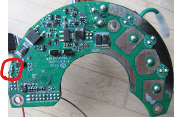
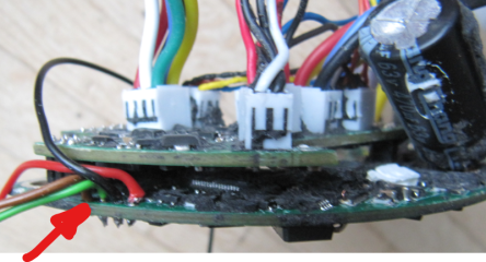
I guess that means full un-potting of the controller is needed, and then removal of the connector pcb to get access?
No, if you have disassembled the controller from the housing, there is enough space to solder in the wires for the debugger.

1784365888949.png

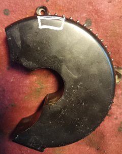
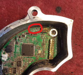
You can try to mill a groove into the aluminium housing to get access to the four pins (+3.3V, GND, SWDIO, SWCLK) from the bottom. But I never tried that.
And of course this not necessary for a standard user at all, as you can flash the firmware non invasive by the BESST/Canable Tool and the display connector ;)

1784366040820.png


1784366509672.png
1784366566389.png
 
Last edited:
Thanks, that was valuable info. Seems doable. By the way, do you have a complete bin-dump available from that board?
The original Bafang firmware I mean
 
what is the difference between Battery current limit and Motor current limit in canable tool v2.2
The motor current defines the torque of the motor and follows the relation
Code:
battery current = motor current * duty cycle

at low speed, you need just a low duty cycle to get a high motor current, as the BEMF of the motor is low. At high speed, the BEMF is high, the duty cycle will be near 1, so battery current and motor current are almost the same.

How can it be related to power of the motor?
That's quite easy. The electrical power is Ubat * Ibat.

The mechanical output power of a BLDC is:

Code:
mechanical power = torque * speed * 2PI 
torque = motor constant * motor current
mechanical power = motor constant * motor current * speed * 2PI

I don't suggest any current settings, we often read about broken clutches, if you set the torque too high ;)
 
Last edited:
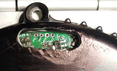
You can try to mill a groove into the aluminium housing to get access to the four pins (+3.3V, GND, SWDIO, SWCLK) from the bottom.
The groove could look like this, even a bit smaller. The hole for the fastening screw gives a good orientation.
The distance from the surface of the housing to the transistor is about 6mm, so you should not mill deeper than 5mm.

IMG_20260718_133412_965~2.jpg
 
Last edited:
The motor current defines the torque of the motor and follows the relation
Code:
battery current = motor current * duty cycle

at low speed, you need just a low duty cycle to get a high motor current, as the BEMF of the motor is low. At high speed, the BEMF is high, the duty cycle will be near 1, so battery current and motor current are almost the same.


That's quite easy. The electrical power is Ubat * Ibat.

The mechanical output power of a BLDC is:

Code:
mechanical power = torque * speed * 2PI 
torque = motor constant * motor current
mechanical power = motor constant * motor current * speed * 2PI

I don't suggest any current settings, we often read about broken clutches, if you set the torque too high ;)
Thanks it helped a lot. As i can see max motor current is always higher than max battery current (mine is 25A) i think max motor will be about 30-40A to start with. Btw what happens if i set it lower than battery max?
 
Noticed that the only difference between the M215 and the M315 bin files are the first main software (MSW) byte (i.e. 0xA800), what is in that position? M215: 0xC9 and M315: 0x81
Checksum CRC-16-CCITT-FALSE at 0xA810, and the checksum cover position 0xA820 till the end of MSW, correct?
 
Btw what happens if i set it lower than battery max?
The max battery current will never be reached, as the duty cycle can't be bigger than 1.


what is in that position? M215: 0xC9 and M315: 0x81
This is the hardware information for the bootloader. It prevents the bootloader to flash a firmware, that's not suitable for the hardware.
In the bin files for the bootloader the first 32 bytes are a header, not the compiled code itself.
We have identified three different bootloader versions since now, each needs a different start address for the interrupt vector table.
 
Last edited:
Back
Top