Batteries, batteries, batteries oh dear lord batteries

Hickbeard

100 W
Joined
Nov 30, 2019
Messages
186
I'm looking at spot welding my next pack and looking at stepping up things.

So reading through various battery threads including pack design mistakes thread (love that thread).

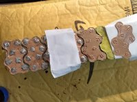
If we use 0.15mm 8mm nickel strip and it has 5a cont current rating then building a 20s pack in the manner in the pic would allow for 50a cont current correct? 10 tabs running in between each P group. Ignore the orange bit for the minute.

So to safely increase current handling of pack we'd want to double up the strips which would double the ability of the pack to draw 100a?

Obviously other things to be considered like battery specs, cabling, etc. But just the physical battery connections this is correct, correct?[emoji2955]

Now if the P group connection has to take more current/have less resistance than the S group connections, could you solder the nickel to a copper bar.

This would then increase current handling without the need to double up nickel strip.

So say I've got a 20s10p pack double thickness nickel across everything. And say I had a 3kw motor. Then say you wanted to set a 250w ish limit. If we programmed the controller to only run 5a battery draw would this pack be too big/too much resistance for such a small current draw?

Could you massively overspec a battery to run a multitude of current ranges. Say moped mode 100a, legalish uk mode 250w/5a, off road ebike mode 50a? BMS would be set to a kinda max limit of the battery in our example 100a. Then controller would limit the current to obtain desired current.

Or does this depend on the type of motor used as well?
2eedb080aabd4864aa0a1b2f1532132d.jpg


Sent from my CLT-L09 using Tapatalk
 
j bjork said:
It is not a problem to have too low ir in the battery, or too much capacity.

Only the opposite is a problem.
OK cool.

So in the above example you could massively increase the range by reducing the current draw.


Sent from my CLT-L09 using Tapatalk
 
10 series connections strips between each P groups in a 20S10P pack will support 50A if each strip is rated for 5A, correct. For parallel connections, supporting 0.1A is already very much overkill.

If you double up on strips for the 10 series connections between each P group by spot welding two layers of strips (20 strips), then yes in theory, that would support 100A.

As for the battery resistance question with a 250W motor...
A battery with less internal resistance is not a limiting factor in any ways. If anything, it's actually a more efficient battery (low internal resistance means low voltage drop, means low heat power loss... Power= dV (voltage drop) x I = R x I².

It's actually the internal resistance of your 36V, 15A peak (7A continuous) controller (or impedance, to be more correct) and 250W hub windings that limits the power to the wheel. if the battery has a very low resistance it wont be much of limiting factor, but a high resistance battery will be the overwhelming limiting factor.

Matador
 
Thanks @Matador

Just looking back at the ampacity spreedsheet in the battery thread to see who did it. it turns out it was created by yourself. Thank you so much. It's very handy.

So...

8mm x 0.2mm nickel = 6.4a. 20 strips between 10 connections would give us 128a max capacity of the nickel series connections.

Could we then swap these 20 connections for 2x 10mm x 1mm copper bars. Each taking 66a so 132a combined? Or are there other factors to consider?

And regarding the motor that's great. So you could just massively overspec battery and motor and run them well under the max "to infinity and beyond" lol.

Sent from my CLT-L09 using Tapatalk
 
Glad the tables are helpfull ! I inspired myself from another user on this forum who made tables in the past (I think his alias on this forum is okashira, not sure, but it was a japanese name for sure), but I based my ampacity off of tables calculations on powerstream.com data. I also wanted to have values for ampacity of strips of other metals than copper and nickel (with different IACS). Finally, ampacity is somewhat variable concept depending on different factors you consider, so I also added resistivity values (in millioms per lenght of strip used) as a more exact reflection of how conductive (or resistive) the metals are.

For the same exact conductor (of a given known lenght, width, thickness and type of metal) the ampacity value will not be the same depending of how much temperature rise you are willing to accept. Same thing with how much voltage drop you are willing to accept for a given conductor. If you want to be more strict on low temp, ampacity will be less. If you want less voltage drop in %, ampacity wil be less too. Powerstream data are conservative values, but they seem to be a well accepted standard, which is why I chose them for reference in ampacity calculations.
Resistivity to me are even more usefull values than the somewhat arbitrary ampacity values. You could calculate the resistance of your whole battery pack knowing the internal resistance of your cells and the lenght of nickel strips you use and their resistivity. Then, you can estimate the voltage drop for a given load you want to pull. If that voltage drop is too much for your application, you know you need to choose beefyer nickel strips (or thicker, or wider). It's quite easy and quick to refer to that table than to pull out a calculator every time.
 
You can definitely use a massively overspeced battery for a given motor. In fact, you batyery will probably live a much longer life, with cells being subjected to less intense discharge rate, less heat and shallower depth of discharge (which reduces battery aging from cycling and from calender aging if they are not allways stored at 100% full charge and/or discharged close to 0%). Ask Tesla about that strategy for making sure batteries have a long lifespan.
 
So if you look at the "Matador table" you can find these values :

For Nickel strips 8mm wide x 0.2mm thick
- ampacity = 6.4 A
- resistivity = 43.7 milliOhms/meter (of strip)

For Copper strips 10mm wide x 1 mm thick
-ampacity = 66A
- resistivity = 1.68 milliOhms/meter

But good luck spotwelding 1.0mm thick strips, especially copper which is the trickiest metal to spotweld.

I assume you meant Copper 0.1 mm thick rather than 1.0 mm thick.

In that case
For Copper 10mm width × 0.1 mm thick
- ampacity : 15 A
- resistivity : 16.8 milliOhms/meter

So 20 strips Nickel 8 x 0.2 mm, yes 128A.
If 2 strips (or rather, buss bars) Copper 10x 1.0 mm, yes 132A.

But, in order to have the best equal current sharing, it way better that EACH of the 10 cells in one row (and going to the nex row of paralleled 10 cells) has it's own separate series connection strip (10 strips or doubled up 10 strips). That's much better that only having two big series connections (2 copper buss bars), because te cells closest to the buss bars will have less resistance in condutive path than the cell further away from the buss bars which will encounter slightly more resistance in their conductive path. But that's all in theory. If you have huge copper busses, you may not see these differences in practice.

Matador
 
There is a very good thread on this forum called something like "common battery pack design mistakes" and it goes into explaining equal current sharing in simple but details too, with multiple eloquent drawing. It helped me quite a lot to understand how to construct battery the best possible way and mistakes to avoid.
 
I was looking into soldering 1-2mm thick busbars in a non spot weld manner.

So ultimately an even distribution of load is the best option, even over less evenly distributed but much bigger series connections. "'

Sent from my CLT-L09 using Tapatalk

 
Always over spec your battery less stress longer life.
https://endless-sphere.com/forums/viewtopic.php?f=14&t=89039
https://endless-sphere.com/forums/viewforum.php?f=14
This thread would be better off in the battery section. Maybe the mods can move it for you ?
 
I just looked and I can't move it.

Yeah over speccing is what I'm taking from all this

Sent from my CLT-L09 using Tapatalk

 
Hickbeard said:
I was looking into soldering 1-2mm thick busbars in a non spot weld manner.

So ultimately an even distribution of load is the best option, even over less evenly distributed but much bigger series connections. "'

Sent from my CLT-L09 using Tapatalk

have you tried soldering the bus bar to a junk cell? might need way too much heat. maybe pre tin everything and use 100 watt iron to get solder job done in 3 seconds. magnets and copper slug tape is 0.2mmx12mm of copper
 
goatman said:
Hickbeard said:
I was looking into soldering 1-2mm thick busbars in a non spot weld manner.

So ultimately an even distribution of load is the best option, even over less evenly distributed but much bigger series connections. "'

Sent from my CLT-L09 using Tapatalk

have you tried soldering the bus bar to a junk cell? might need way too much heat. maybe pre tin everything and use 100 watt iron to get solder job done in 3 seconds. magnets and copper slug tape is 0.2mmx12mm of copper
Soldering will be done before cells are introduced.

Sent from my CLT-L09 using Tapatalk

 
For soldering cells... first lightly sand the cell terminals with 120-240 grit sand paper (helps with solder adhering rapidely).
Then, apply generous flux rosin to cell terminals.
Then pre-tin the cell terminal with some solder wire (dont apply iron for more than 2-3 seconds at most... better to let it cool and reapply iron after it cooled than to leave the iron on for 5 seconds and risk ruining the cell).
Pre-tinnin will greatly help in the soldering of bus bar.... So also pretin the busbar before soldering it to the cells.

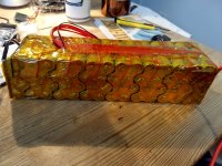
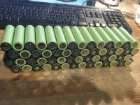
I did solder a whole 14S4P battery with copper sheets
More detailed pictures here: https://endless-sphere.com/forums/viewtopic.php?f=2&t=93576&start=75#p1414963
f.jpgm.jpg

Turned out great. To this day, all my cells are still balanced within 0.003 volts. But I was extremely carefull not to overheat the cells. And cooled each solder joint right after hardened after blowing air on them by further rapidely cooling them wit with a sponge wetted with isopropyl alcoohol. Never applied iron for more than 3 seconds. I used a 140W soldering iron.

Matador
 
999zip999 said:
I would use extra paper gaskets on the POS. side
As the whole can is neg and just the nipple is pos..

Agreed, that's a must or a short circuit disaster is just waiting to happen.

Matador
 
Like this. Put fish-paper nipples on the positive side of the can or you will melt the plastic heatshrink and create a massive short-circuit.BATT4.jpg
Matador
 
Matador what you think ?
https://batteryhookup.com/collections/cell-level-nickel-fuse/products/nickel-fuse-2p-wide-continuous-roll-by-the-foot-18650-cell-level-fusing
I think overkill for bike battery but then again I don't use a BMS..
Plus
https://endless-sphere.com/forums/viewtopic.php?f=31&t=92223#p1348614
 
999zip999 said:
Matador what you think ?
https://batteryhookup.com/collections/cell-level-nickel-fuse/products/nickel-fuse-2p-wide-continuous-roll-by-the-foot-18650-cell-level-fusing
I think overkill for bike battery but then again I don't use a BMS..
Plus
https://endless-sphere.com/forums/viewtopic.php?f=31&t=92223#p1348614

Good question. Honestly, I have not yet experimented with individual cell fusing. I tend to like everything related to over engineering of batteries. However I'm still ambivalent about individual cell fusing because I always wondered if that could cause unecessary added resistance in a pack. My logic is that fuse break because at a certain current value, they burn. And they burn because they have relatively high resistance. And even though the current that goes through fuse normally is much lower, there will still be some loss because deltaV = R x I, and deltaP (watt loss in heat) = R x I^2 (ohms law). So for huge pack like in a Tesla car, the heat loss is probably insignificant, as individual cells see quite low current. But in relatively much smaller ebike packs, the current per cell is going to be higher... And as the heat loss is proportionnal to the square of the current (dP = U x I^2), if you if you ask for example 4 amps per individual cell instead of 2 amps (aka doubling current), the heat loss quadruples ! At what point is the heat loss enough to burn/break the fuse, I'm not sure... But i thinks I'd be more inclined to use individual cell fusing technology on huge battery packs. But as I say, I've noy experimented with it, and my opinion could change. I've certainly noticed individually fused commercial e-Bike battery packs from EM3 EV, and they look beautifully built !

Matador
 
All in all I think individually fusing cell is worth it if the max current seen by cells in normal battery usage is to be manyfolds lower than the current you'd want a fuse to burst.

For example if normal battery operations means an individual cell sees 5 amps, i'd want the fuse to burn at 20 amps per cell...
That way, current needs to be 4 times higher than normal max nominal current for a fuse to burn. Heat power loss would be 16 times lower than that necessary to reach the fuse flash point at max nominal current (4^2=16).
Let's say the fuse burns at 16 watts (at 20 amps) well then at normal max current (5 amps) you'd "only" loose 1.0 watts per cells.

So let's for a 14S10P pack that would give a max current of 50A, you'd only loose 280W of heat loss du to the added resistances of the fuses 280 fuses Well my numbers are all just fictionnal, but It certainly is an example that makes me think of the potential downsides of individual cell fusing.

I must say though my calculation here is oversimplified, as resistance in series do not add the same way as resistance in parallel.
Resistances in series just add up, but to add resistances in parrallel, you need to make the sum of all the inverse of the values (1/Rtot = 1/Ra + 1/Rb + ... + 1/Rj). So the real thing would be 5.6 W 😒😁
 
I understand what you're saying and agree especially for our high-wattage 5000 w bikes. And with a small lightweight pack to propell a ebike.
Do they just put the fuse on the positive in or do they put a fuse on the negative end also ?
 
999zip999 said:
Do they just put the fuse on the positive in or do they put a fuse on the negative end also ?

One fuse per cell is enough. No need to do both yhe + and - terminals. Doing both is not usefull and just adds more rrsistance IMHO. So one would have to do on side with the fused nickel strip you gave a link for and the other side with conventionnal (unfused) nickel strips.
 
Back
Top