• Howdy! we're looking for donations to finish custom knowledgebase software for this forum. Please see our Funding drive thread

Battery Charger EMC-400 - Dead but fixable?

danoussh

10 mW
Joined
Aug 20, 2013
Messages
23
Location
France
Dear Community,

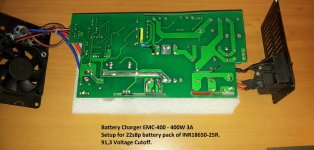
I've one of my burnt my charger for my 22s8p 18650INR-25R battery pack. The charger is a "Battery Charger - EMC-400 - 400W 3A".

Let me explain what happened. I plugged in the charger to the house 230V AC wall plug, the chargers' LED turned on. I left it like that for less then 10 seconds, and I plugged in my battery pack to start charging.
About 2 - 3 seconds in, the chargers' LED started flickering and it made some torturing noise. I quickly unplugged the battery from the charger and then the charger from the wall plug. I may recall a very small amount of smoke, but really not much, just enough for two burnt resistors. Since then the charger doesn't turn on anymore.

I read many different threads, and they all say the same thing; Current Inrush!!
What they don't say the same is what is the correct plugging steps.

But right now I would like some guidance towards fixing the charger.
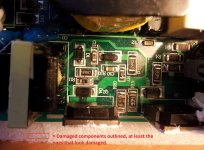
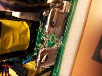
You see in these photos, that there are small components that seems to have burnt. At least we can't read their ratings/values anymore.

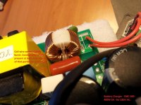
Capacitor C11 and resistor R11 and R20 are the damaged components. And maybe the inductor, but not sure about that as I still have conductivity between the entrance and the exit of the inductor. BTW, what are inductor used for in these circuits?
IMG_20150821_124941.jpg
IMG_20150821_125217.jpg
IMG_20150821_125248.jpg
IMG_20150821_125355.jpg

I'm going to bring my new chargers to an electronic shop will and asked the guy if he has the same components available. Then will try to replace and solder them back.
I hoping to document this, as I haven't see many threads like this for an EMC-400.

I remember reading many post from Dnmun, he explains things very well.

Best regards,
Danoussh

PS: Why do I also have sparks when plugging the battery to the controller, when I connect the pre-charge cable that has an XT90. I though the whole point of these connector was to limit voltage potential difference using a small resistor and thus removing the spark. But I still seem to have a small sparks, which means my controllers' caps are charging up very quickly right? The value of the XT90 resistor seems to be only 10ohms I think from memory. That doesn't seem much.
 
usually it is cheaper to buy a new one than hire a greek tv repairman to fix it. the parts would be about $10 normally but most people do not have them. especially the little surface mount base resistors but it can be replaced with a regular axial leaded resistor soldered in place.

the switching transistors are FJP13009 and both of those npn transistors need replaced. TO247 size. big ones. R20 is the same as R9 2R20 2.2 ohm base resistor. those other diodes as well as the surface mount cap may be bad.

if you look closely you can see the circuits to both of the transistors are identical. it is called a totem pole because they are stacked one on top of the other between the 340V DC off of the input caps and ground. these two transistors make up the push/pull driver of the oscillator circuit that pushes current through the primary winding of the transformer. they are driven by the smaller transformer which itself has two npn transistors driven by the TL494 IC current controller.

the 'coil' on the input is an inductor placed there to stop the rf noise from going backwards into the 240V AC supply. is the wired burned where the imperfection is present on the surface?
 
I found a page from another site, but i found the link on Endless-sphere.
http://www.avdweb.nl/solar-bike/ele...eight-lifepo4-ebike-battery-charger-800g.html

The guy post a reverse engineered schematic of a E-400.
Can anyone confirm this is the same schematic as the EMC-400?

It looks very much the same. But I'm not sure as I'm no electronic wizard.

I tried to look for the default components' values, but found nothing when comparing with my other EMC-400 charger.
IMG_20150828_144401.jpg


EDIT:

Thanks for the response Dnmun, I saw your response only when I submitted my own response.


dnmun said:
usually it is cheaper to buy a new one than hire a greek tv repairman to fix it. the parts would be about $10 normally but most people do not have them. especially the little surface mount base resistors but it can be replaced with a regular axial leaded resistor soldered in place.
This is what I was expecting to do, replace with normal components, but you may be right, buying a new is probably better.

the switching transistors are FJP13009 and both of those npn transistors need replaced. TO247 size. big ones. R20 is the same as R9 2R20 2.2 ohm base resistor. those other diodes as well as the surface mount cap may be bad.
Sounds like, their may be more damage than what I noticed. How do you know that those transistors are dead also?

if you look closely you can see the circuits to both of the transistors are identical. it is called a totem pole because they are stacked one on top of the other between the 340V DC off of the input caps and ground. these two transistors make up the push/pull driver of the oscillator circuit that pushes current through the primary winding of the transformer. they are driven by the smaller transformer which itself has two npn transistors driven by the TL494 IC current controller.

the 'coil' on the input is an inductor placed there to stop the rf noise from going backwards into the 240V AC supply. is the wired burned where the imperfection is present on the surface?
Yes, I think it is burnt, at least it seemed to have warmed up enough to make that mark. But as I said above, I still have conductivity, but then again the wire may be damadge enough to change the effet of the inductor maybe?
 
the coil should not get hot in any case. it is just a wire.

if it is almost broken you can either solder the void closed or unsolder the coil totally and then unwind that first loop to get some slack so you can then cut off the break and put the coil back in place with the winding on one side a little shorter or remove equal amounts on each side and reinsert it.

i know the transistors are dead because of how they overheated the pcb. you can see the section on the outside has sagged from the heat and when they go bad they blow out the base resistor too like you see there. the diode label RS2M is most probably bad too. check it with a diode tester. compare to the one on the right across the collector emitter of the other totem pole transistor. R7 is the same as R11 2701 is 2700 ohms. you can verify with your meter.

you should be able to see how all those components are identical and connected to the each of the transistors the same way.

this is a common failure mode. hiside switching transistor shorts out and take base resistor with it.

see if google will tell you what the RS2M diode is. it may be 200V or it may be 2,000 V but it does look discolored so i suspect it burned up too. in fact, that may be why the transistor failed. where that flyback diode failed first.
 
Thanks Dnmun for all your information.

I will try to fix this this weekend.
If I ever successfully fix this charger, I will post all the info.

Best regards,
Danoussh
 
i have the parts. if you have any skills at soldering you can replace that surface mount base resistor with a regular 2.2 ohm 2W resistor but in that case i would recommend replacing both the base resistors along with the two switching transistors at the same time. all those parts have to be identical to make the oscillator remain balanced between hiside and loside.

i have the parts here too if you need them. i can show you how to test the hiside transistor with the diode tester too if you wanna do that.

but verify that flyback diode across the hiside transistor is still functional first with your diode tester.

you can cut the legs off of that hiside transistor first and remove the stumps from the holes by heating the solder and whacking the pcb on the bench and they will fly out along with the solder.

ps: edited, i am thinking now that maybe the switch which is in the loside transistor base drive circuit may add enuff resistance to the base resistor to cause these problems so maybe it could be rebuilt and bypass that switch to increase the chances it will last longer. never thought about this before. always considered that switch a bonus because of how it turns off the charger.

ebike1 guy in korea had his emc400 go bad too and i wonder if it is the same except his did not appear to be blown up.
 
I've just come back from the shop, it was closed for annual holidays. They do this alot in France. I just did 30km to find out it was closed. Lol :lol:

dnmun said:
i have the parts. if you have any skills at soldering you can replace that surface mount base resistor with a regular 2.2 ohm 2W resistor but in that case i would recommend replacing both the base resistors along with the two switching transistors at the same time. all those parts have to be identical to make the oscillator remain balanced between hiside and loside.

i have the parts here too if you need them. i can show you how to test the hiside transistor with the diode tester too if you wanna do that.
I would love to ear about how you test the hiside transistor, that would be great. Good knowledge for ES forum. I not sure if I will accept your offer about the components as it may just be cheaper to get them from the shop once it opens again, but then again he mite not have the right components.

but verify that flyback diode across the hiside transistor is still functional first with your diode tester.
I will perform this test tomorrow with a Velleman DVM 68. I think this is the right tool, I'll make sure of this tomorrow when I start working on this.

you can cut the legs off of that hiside transistor first and remove the stumps from the holes by heating the solder and whacking the pcb on the bench and they will fly out along with the solder.
This is actually a great idea, to cut the legs off first, and then remove each leg of component separately!!

ps: edited, i am thinking now that maybe the switch which is in the loside transistor base drive circuit may add enuff resistance to the base resistor to cause these problems so maybe it could be rebuilt and bypass that switch to increase the chances it will last longer. never thought about this before. always considered that switch a bonus because of how it turns off the charger.
When you talk about a "switch", you meen a physical switch, the one that is placed on the side, just underneath the female AC power connector?

ebike1 guy in korea had his emc400 go bad too and i wonder if it is the same except his did not appear to be blown up.
I'll have a look for this member and his topic, and get informed about it.
 
you can call them and ask them if they have the transistors. the FJP13009 comes in two sizes. you want the high current one. the package is called TO3P and is larger than the smaller TO220 package so tell them that is what you want.

the 2.2ohm surface mount resistor has to be a big one 2W i expect and is very unusual to be stocked.

i have mailed parts like this to a guy in france before. or you can buy them off ebay but the little base resistor will be hard to find. the surface mount diode is this one:

http://www.farnell.com/datasheets/1662564.pdf
 
i found some of my 2.2 ohm 2W resistors. these are axial leaded resistors which i suspect is all you will find so ask your guy there if he has these.

mouser p/n: 594-5083NW2R200J

vishay PR02000202208JR500

and you can solder these to the pcb where the little surface mount resistor is located and connect the other end of the resistor to the base leg of the npn transistor. it does not have to be soldered back down to the pcb on that end. you just bypass the trace to the base leg and solder it directly to the base leg.

and bypass that switch altogether. i am now gonna recommend people do this to all of these chargers with the switch.

i think this could be the reason they blow up the hiside transistor by introducing extra impedance into the base resistor circuit of the loside transistor. that would force more current through the hiside than the loside transistor and imbalance the oscillator so it ends up overheating or overvolting somehow.

heath knows them better than me or maybe someone else knows these push/pull amplifier circuits.
 
Back
Top