Best. Headlight. Ever. Taillight, too!

mystryda

10 W
Joined
Jul 11, 2017
Messages
69
Location
Germany
Buttom line up front: this headlight is the brightest that I've ever seen, much less used, and because it has a sharp cutoff it doesn't blind oncoming traffic. The taillight is really good, but it's also a fair bit of work to get all together. The headlight is low-hanging fruit that I think most people could get going with very little trouble. The taillight is challenging.


Headlight on a dark road:
[youtube]XqsgoLw8PKQ[/youtube]

Nighttime taillight fading:
[youtube]UpD_2eAJcXE[/youtube]

Daytime taillight flashing:
[youtube]VGiX7Yh7mGc[/youtube]


On my commute I'm frequently on a shoulder that's littered with construction debris, furniture, glass, you name it. It's a busy road with a lot of commercial and industrial traffic. In my last commute I was content with my Chinese knock-off Magicshine (one front, one back, both with 10 deg. high, 40 deg. wide Fresnel lens), but for this road I simply want more light on the pavement.

With a few exceptions, most of the lights marketed to cyclists have a conical "flood" pattern, where a lot of the light is not only "wasted" in the upwards direction but can prove distracting or even blinding to oncoming traffic.

My solution was to select a 5 3/4" motorcycle headlight with a hard cutoff in the distribution pattern (DOT certified). I bought a Chinese knock-off of a Harley Daymaker: https://www.amazon.com/gp/product/B01L1SK9Y6/

I also wanted to improve my rear lighting, so I ordered a real of 5630 SMD strip lights "16ft/5M 5630 Waterproof 300 LED Light Strip Flexible Ribbon DC12V LED Tape Lamp" https://www.ebay.com/itm/401516721115

As the linear regulator in the headlight gives full power down to 10.5V, had I just been content with the headlight, it would have been much easier from a power and control standpoint, as simple as connecting it 18650s is 3S, possibly with a switch to toggle between high and low beams. To improve efficiency, you could use a switch DC/DC power converter to bring your battery voltage down to a steady 10.5V.
XL4015-based switching DC/DC converters: https://www.amazon.com/gp/product/B078JWWDV1/

I wanted more, and here's how I went about it:

4S4P 18650 (fabricated with cells from a pair of cheap 8-cell laptop batteries off eBay) gives me 14.4V, nominal.

One DC/DC converter takes mains down to 10.5V for the headlight. So that I could make the light flash off by asserting 5V, I desoldered the screw-down terminals on the input so that I could get to the XL4015 chip and then lifted pin 2 to mimic the schematic (resister, diode soldered directly to the pin and each other) on page 8 of the datascheet:
http://www.xlsemi.com/datasheet/XL4015%20datasheet.pdf
Output of the converter goes to the handlebars where a SPDT switch selected high or low beams. I used 3-wire marine/waterproof pigtails (like you find on some aftermarket headlights) between the switch and the headlight itself so that I could disconnect the headlight for ease of installation and service:
https://www.amazon.com/gp/product/B07VHHXKSX/


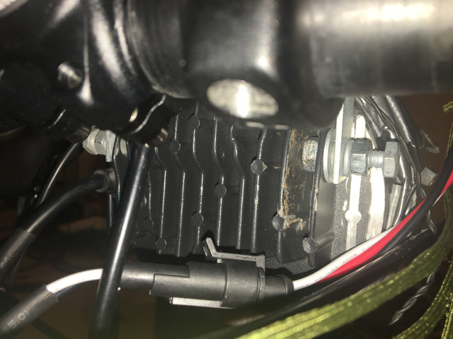
Use a hacksaw and dremel tool, I cut the last two fins off each side of headlight. I drilled holes in the larger fin that was now readily accessible and installed galvanized 1/4" hardware: nut, locknuts, cut washers to distribute pressure evenly, all connected to angle brackets to that go up to clamps mounted on the "skis" of the aerobars (after a couple wraps of rubber to pad and make snug):
https://www.ebay.com/itm/Gs-Power-Tube-Clamp-Brackets-Choices-1-1-25-1-75-2-Inch-Mount-Led-Light-Bar-R/303245443745

The taillight is way more complicated:

Another XL4015 DC/DC converter, now giving "always on" 12VDC. Output goes back to the taillights, but we'll get to that. Output also goes to an Arduino Nano, which has an onboard regulator to get down to 5Vcc. Inputs are buffered with bypass caps and current limiting resistors. Outputs have current limiting resistors. Connected to the inputs are four toggle switches: left and right "turn signal" (on the handlebars) as well as headlight steady/flash and taillight mode on the control box (under/behind the seat). Four outputs of the Arduino plus the ground that I sent from the DC converter all go to four MOSFETs at the back of the bike, that are shielded from weather as well as encapsulated in heatshrink. 12VDC hot gets distributed to the LEDs, and grounds from the LEDs go to the MOSFETs. (If this isn't making sense, sorry: ask a question or look it up.) I ran 12" strips on the twe verticals of the rack mounts plus the middle of the fender, and then I made a 18 LED patch that's right below the saddle bag.

From the handlebars I can toggle the left and right turn signals switches (or both to run an entirely different program) plus select high or low beams. By reaching under my rump I can select steady (night/dusk) or pulsing (daytime) for the headlight; and either flashing (daytime) or fading (night/dusk) for the taillight.


Wires are jacketed in the sheathing of parachute cord protection, separation, abrasion resistance, and so that I could tie off the ends of the cord for strain relief. As I previously mentioned, the aluminum headlight casing is bolted to tubular brackets for the handlebars with galvanized 1/4" hardware. All the circuitry fit snugly into a project box that hangs from the rails of my saddle. (For the Arduino to fit, it's on standoffs so that it slightly overlaps one of the XL4015 boards. If I were to do this again, I would get a bigger enclosure; mine is 100*66*27mm, $5 on eBay shipped from Shanghai.)

(Yes, my seatpost is "backwards." It lets me get my hips farther forward.)


Ask questions or ask for specific pictures.
 
Yep. I've been running one for over a year now. There are now some other variations and some with a daytime Halo feature that would be worth looking at. I just use a standard 12 v dc converter from my 36 volt batteries and a three-way motorcycle switch (on-off-on) for high-off-low. XT60 connectors.

[youtube]xc-OmweGZrM[/youtube]
 
Code for the Arduino, in case anybody wants to check it out:
(Very easy to breadboard: use jumpers instead of switches, plus 5 resistors and 5 leds.)

//https://github.com/MajicDesigns/MultiBlink/blob/master/Multi_Blink4/Multi_Blink4.ino
/*
Multi_Blink4
Blink lots of LEDs at different frequencies simultaneously, include fades, delays
and loops in patterns
Marco Colli - June 2013

Demonstrates
- the way to carry out multiple time based tasks without using the delay() function
- the use of structures (and structures within structures)
- a data driven approach to programming to create compact, reusable code
How this works
==============
This sketch separates the HOW (code) and the WHAT (data) of multi-tasking
the blinking of LEDs. How we blink LEDS is the same no matter what LED we are
blinking, so this can be defined independently. What outputs the blinking applies
to and how long it lasts is separately defined and applied to the code.
This data driven approach is applicable to any number of situations
where repeated independent actions need to be carried out simultaneously.

The code used in this sketch implements a general approach to manipulating
digital outputs based on a Finite State Machine. What to do in each state of the
FSM is defined using the constants MB_*, arranged in data tables that are 'run'
by the FSM. To change the behaviour of the software, the data table is modified
for the new requirements.
The data table (defined in T[] below) consists of an arbitrary length array of
ledTable structures that define the parameters for the digital output and
'remember' the current FSM parameters - its current state and the time for the
next state transition.
Each ledTable entry has associated with it up to MAX_STATE states (defined
using stateDef structures) that specify what the FSM will do when it is in
that state. To change the number of allowable states, modify the MAX_STATE
constant. The state value is just the array subscript.
The tables can be statically or dynamically initialised. In this code the
patterns are defined statically in the T[] tables.
Defining stateDef entries
=========================
- MB_ON and MB_OFF
------------------
Keep the LED on or off for the specified time. The entry
{MB_ON, 25, 0}
keeps the digital output high for 25 milliseconds.
- MB_LOOP
-------
Makes the pattern loop back to the nominated array element in the pattern for the
specified number of times.
The macro LOOP_PARAM(s, c) is used to pack the loop parameters into the data word,
where s is the state (array index, zero based) to loop back to and n is the total
number of times to execute the loop. Use the value 255 to loop indefinitely. Macros
LOOP_STATE_GET() and LOOP_SP_GET() are used to unpack this data.
The entry
{MB_LOOP, LOOP_PARAM(0, 3}
causes the FSM to loop back to element 0 and repeat it 2 more time (3 total).
- MB_FADE_ON and MB_FADE_OFF
--------------------------
Fade a PWM output from a starting value to an end value (both a number 0 to 255),
keeping each state for the specified time. This is, in effect, a special kind
of loop.
The macro FADE_PARAM(s, e) is used to pack the fade effect parameters into the data
word, where s is the starting PWM value and e is the end PWM value. The macros
FADE_START_GET() and FADE_END_GET() are used to unpack these data.
The entry
{MB_FADE_OFF, 45, FADE_PARAM(30, 1), 0}
fades a PWM output from a starting value of 30 to 1, cycling one PWM value each
45 milliseconds.
- MB_STOP
-------
Stop executing the pattern.
- MB_GOTO
-------
Go to the state specified as the next state. The entry
{MB_GOTO, 55, 2, 0}
goes to state 2 after 55 milliseconds.
Building a ledTable
===================
Whilst ledTable entries are defined and run independently, the patterns are constructed
by considering and planning how these independent lights interact for the viewer.
So this data for output pin 3
{ 3, 0, 0, {{MB_ON, 25, 0}, {MB_OFF, 25, 0}, {MB_LOOP, LOOP_PARAM(0, 3}, {MB_OFF, 300, 0}}, 0 },
does this:
State 0 is {MB_ON, 25, 0} - LED on for 25 ms
State 1 is {MB_OFF, 25, 0} - LED off for 25 ms
State 2 is {MB_LOOP, LOOP_PARAM(0, 3)} - Loop back to state 0 and repeat it 2 more time (3 total)
State 3 is {MB_OFF, 300, 0} - LED off for 300 ms - this is a delay while the 'other' LED blinks
So if we want to have a paired LED that works in tandem with this one and is blinking
while this one is off, we need to implement the logic
State 0 is {MB_OFF, 300, 0} - LED off for 300 ms - this is a delay while the 'other' LED blinks
State 1 is {MB_ON, 25, 0} - LED on for 25 ms
State 2 is {MB_OFF, 25, 0} - LED off for 25 ms
State 3 is {MB_LOOP, LOOP_PARAM(1, 3)} - Loop back to state 1 and repeat it 2 more time (3 total)
which provides the following table entry for output pin 4:
{ 4, 0, 0, {{MB_OFF, 300, 0}, {MB_ON, 25, 0}, {MB_OFF, 25, 0}, {MB_LOOP, LOOP_PARAM(1, 3)}}, 0 },
So if we look at them as a pair
{ 3, 0, 0, {{MB_ON, 25, 0}, {MB_OFF, 25, 0}, {MB_LOOP, LOOP_PARAM(0, 3)}, {MB_OFF, 300, 0}}, 0 },
{ 4, 0, 0, {{MB_OFF, 300, 0}, {MB_ON, 25, 0}, {MB_OFF, 25, 0}, {MB_LOOP, LOOP_PARAM(1, 3)}}, 0 },
Similarly, more complex patterns and inteactions can be planned and configured
into the data tables.
*/


#include <Arduino.h>


/*Headlight flashing code, from: https://forum.arduino.cc/index.php?topic=452096.0
* ----------------------------------
* -----------------------------------
* -----------------------------------
*/

struct Flasher {
const byte pin;
const uint32_t *sequence;

int sequenceIndex;
boolean flashOn;
uint32_t startTime;

Flasher(byte attachPin, const uint32_t *sequence) : pin(attachPin) , sequence(sequence)
{
flashOn = true;
sequenceIndex = 0;
startTime = millis();
}

void setup() {
pinMode(pin, OUTPUT);
//start with the LED on
digitalWrite(pin, HIGH);
}

void loop() {
if(millis() - startTime >= sequence[sequenceIndex]) {
sequenceIndex++;
if(sequence[sequenceIndex] == 0) {
sequenceIndex = 0;
}
startTime = millis();

flashOn = !flashOn;
digitalWrite(pin, flashOn ? HIGH : LOW);

}
}
};


/* Back to the State Machine for the taillights! -----------------------------------
* -----------------------------------
* -----------------------------------
*
*/

// State values for the Finit State Machine (FSM)
#define MB_NULL 0
#define MB_ON 1
#define MB_OFF 2
#define MB_FADE_ON 3
#define MB_FADE_OFF 4 // stateDef.data is the start and end PWM Setting - use FADE_* macros
#define MB_LOOP 5 // stateDef.data is the next state position and counter setpoint, use LOOP_* macros
#define MB_GOTO 6
#define MB_STOP 9

// Special counter initialisation value (undefined)
#define CTR_UNDEF 255

// The number of state definitions for each element of the LED table.
// There are up to MAX_STATE transitions allowed per element of the LED table. If more than the
// number defined are required, change this constant. All the table entries will get MAX_STATE
// transitions, even if they are not used, so big numbers use up lots of memory!
#define MAX_STATE 6

#define ARRAY_SIZE(x) (sizeof(x)/sizeof(x[0]))

// Macros used to pack and unpack 8 bit values into a 16 bit data word
#define FADE_PARAM(s, e) (((s) << 8) | (e))
#define FADE_START_GET(n) highByte(n)
#define FADE_END_GET(n) lowByte(n)

#define LOOP_PARAM(s, c) (((s) << 8) | (c))
#define LOOP_STATE_GET(n) highByte(n)
#define LOOP_SP_GET(n) lowByte(n)

// Data structures for the state definition and the LED table
typedef struct
{
uint8_t stateID; // state value for this state to be active (MB_* defines)
uint16_t activeTime; // time to stay active in this state in milliseconds
uint16_t data; // data store for state context information/parameters (depends on MB_*)
uint8_t counter; // generic counter for the state context information. CTR_UNDEF is special value.
} stateDef;

typedef struct
{
uint8_t ledPin; // Arduino I/O pin number
uint8_t currentState; // current active state
uint32_t nextWakeup; // the 'time' for the next wakeup - saves the millis() value
stateDef state[MAX_STATE]; // the MB_* state definitions. Add more states if required
} ledTable;

#define SWITCH_TABLE 7 // switch between patterns using this input

// Blink Table T - Modify this table to suit whatever the output requirements are
// Add or delete lines as required to achieve the desired effects.
// Have multiple tables and switch between them to create different effects based on external inputs
// To add additional states the structure in the header file needs to be modified
//
//Pin St WUp State 0 State 1 etc


//ledTable T1[] =
//{
// // Alternate double flashers, like emergency vehicles
// { 5, 0, 0, {{MB_ON, 50, 0, 0}, {MB_OFF, 100, 0 ,0}, {MB_LOOP, 0, LOOP_PARAM(0, 4), 0}, {MB_OFF, 800, 0, 0}, {MB_NULL, 0, 0, 0}} },
// { 6, 0, 0, {{MB_OFF, 100, 0, 0}, {MB_ON, 50, 0, 0}, {MB_LOOP, 0, LOOP_PARAM(0, 4), 0}, {MB_OFF, 800, 0, 0}, {MB_NULL, 0, 0, 0}} },
// { 9, 0, 0, {{MB_OFF, 800, 0, 0}, {MB_ON, 50, 0, 0}, {MB_OFF, 100, 0, 0}, {MB_LOOP, 0, LOOP_PARAM(1, 4), 0}, {MB_NULL, 0, 0, 0}} },
// { 10, 0, 0, {{MB_OFF, 800, 0, 0}, {MB_OFF, 100, 0, 0}, {MB_ON, 50, 0, 0}, {MB_LOOP, 0, LOOP_PARAM(1, 4), 0}, {MB_NULL, 0, 0, 0}} },
//};

//////// Left Turn Flashers
ledTable T1[] =
{
#define GLOW 100
#define FAINT 5
//commented out "Mustang Pattern"
// { 9, 0, 0, {{MB_ON, 200, 0, 0}, {MB_OFF, 500, 0 ,0}, {MB_OFF, 200, 0, 0}} },
// { 6, 0, 0, {{MB_OFF, 150, 0, 0}, {MB_ON, 200, 0, 0}, {MB_OFF, 550, 0, 0}}, },
// { 5, 0, 0, {{MB_OFF, 350, 0, 0}, {MB_ON, 350, 0, 0}, {MB_OFF, 200, 0, 0}}, },
// { 10, 0, 0, {{MB_OFF, 50, 0, 0}, {MB_ON, 50, 0, 0}, {MB_LOOP, 0, LOOP_PARAM(0, 3 )}, {MB_OFF, 300, 0, 0}}, },

{ 9, 0, 0, {{MB_FADE_ON, 1,FADE_PARAM(GLOW, GLOW), 0}} },
{ 6, 0, 0, {{MB_FADE_ON,1,FADE_PARAM(FAINT, FAINT), 0}} },
{ 5, 0, 0, {{MB_ON, 500, 0, 0}, {MB_OFF, 500, 0, 0}}, },
{ 10, 0, 0, {{MB_OFF, 25, 0, 0}, {MB_ON, 25, 0, 0}, {MB_LOOP, 0, LOOP_PARAM(0, 1 )}, {MB_OFF, 800, 0, 0}}, },


// { 12, 0, 0, {{MB_OFF, 200, 0, 0}, {MB_OFF, 40, 0, 0}, {MB_ON, 40, 0, 0}, {MB_LOOP, 0, LOOP_PARAM(1, 2 )}}, },
};

//////// Right Turn Flashers
ledTable T2[] =
{
#define GLOW 100
#define FAINT 5
// { 5, 0, 0, {{MB_ON, 200, 0, 0}, {MB_OFF, 500, 0 ,0}, {MB_OFF, 200, 0, 0}} },
{ 5, 0, 0, {{MB_FADE_ON, 1,FADE_PARAM(GLOW, GLOW), 0}} },
{ 6, 0, 0, {{MB_FADE_ON,1,FADE_PARAM(FAINT, FAINT), 0}} },
{ 9, 0, 0, {{MB_ON, 500, 0, 0}, {MB_OFF, 500, 0, 0}}, },
{ 10, 0, 0, {{MB_OFF, 25, 0, 0}, {MB_ON, 25, 0, 0}, {MB_LOOP, 0, LOOP_PARAM(0, 1 )}, {MB_OFF, 800, 0, 0}}, },
// { 12, 0, 0, {{MB_OFF, 200, 0, 0}, {MB_OFF, 40, 0, 0}, {MB_ON, 40, 0, 0}, {MB_LOOP, 0, LOOP_PARAM(1, 2 )}}, },
};

////////Emergency Flashers
ledTable T3[] =
{
#define T_OFF 40
#define T_ON 20
#define T_FADE 1
#define T_WAIT 500
// Fading LED chaser (all PWM pins)
//{ 5,0,0, {{MB_OFF,(T_OFF*0),0,0}, {MB_ON,T_ON,0,0}, {MB_FADE_OFF,T_FADE,FADE_PARAM(150,0),0}, {MB_OFF,T_WAIT+(T_OFF*5),0,0}, {MB_NULL,0,0,0}} },
//{ 6,0,0, {{MB_OFF,(T_OFF*1),0,0}, {MB_ON,T_ON,0,0}, {MB_FADE_OFF,T_FADE,FADE_PARAM(150,0),0}, {MB_OFF,T_WAIT+(T_OFF*4),0,0}, {MB_NULL,0,0,0}} },
{ 9,0,0, {{MB_OFF,(T_OFF*2),0,0}, {MB_ON,T_ON,0,0}, {MB_FADE_OFF,T_FADE,FADE_PARAM(150,0),0}, {MB_OFF,T_WAIT+(T_OFF*3),0,0}, {MB_NULL,0,0,0}} },
{ 10, 0, 0, {{MB_FADE_ON,1,FADE_PARAM(5, 5), 0}} },
// { 10,0,0, {{MB_OFF,(T_OFF*4),0,0}, {MB_ON,T_ON,0,0}, {MB_FADE_OFF,T_FADE,FADE_PARAM(150,0),0}, {MB_OFF,T_WAIT+(T_OFF*1),0,0}, {MB_NULL,0,0,0}} },
// { 11,0,0, {{MB_OFF,(T_OFF*5),0,0}, {MB_ON,T_ON,0,0}, {MB_FADE_OFF,T_FADE,FADE_PARAM(150,0),0}, {MB_OFF,T_WAIT+(T_OFF*0),0,0}, {MB_NULL,0,0,0}} },
};

//////// Taillight Pattern 4: Nighttime
ledTable T4[] =
{
#define T_OFF 1535
#define T_ON 20
#define T_FADE 50
#define T_WAIT 500
#define GLOW 12
// Aircraft wing tip flashers
// { 5, 0, 0, {{MB_ON, 20, 0, 0}, {MB_OFF, 50, 0, 0}, {MB_LOOP, 0, LOOP_PARAM(0, 3), 0}, {MB_ON, 250, 0, 0}, {MB_OFF, 450, 0, 0}} },
// { 6, 0, 0, {{MB_OFF, 450, 0, 0}, {MB_ON, 20, 0, 0}, {MB_OFF, 50, 0, 0}, {MB_LOOP, 0, LOOP_PARAM(1, 3), 0}, {MB_ON, 250, 0, 0}} },
// Revolving lighthouse beam

{ 5, 0, 0, {{MB_FADE_ON,(T_OFF*0),FADE_PARAM(GLOW, GLOW), 0}, {MB_FADE_ON, T_FADE, FADE_PARAM(1, 30), 0}, {MB_ON, 70, 0, 0}, {MB_FADE_OFF, T_FADE, FADE_PARAM(30, 1), 0}, {MB_FADE_ON,(T_OFF*2),FADE_PARAM(GLOW, GLOW), 0}} },
{ 6, 0, 0, {{MB_FADE_ON,(T_OFF*1),FADE_PARAM(GLOW, GLOW), 0}, {MB_FADE_ON, T_FADE, FADE_PARAM(1, 30), 0}, {MB_ON, 70, 0, 0}, {MB_FADE_OFF, T_FADE, FADE_PARAM(30, 1), 0}, {MB_FADE_ON,(T_OFF*1),FADE_PARAM(GLOW, GLOW), 0}} },
{ 9, 0, 0, {{MB_FADE_ON,(T_OFF*2),FADE_PARAM(GLOW, GLOW), 0}, {MB_FADE_ON, T_FADE, FADE_PARAM(1, 30), 0}, {MB_ON, 70, 0, 0}, {MB_FADE_OFF, T_FADE, FADE_PARAM(30, 1), 0}, {MB_FADE_ON,(T_OFF*0),FADE_PARAM(GLOW, GLOW), 0}} },
{ 10, 0, 0, {{MB_OFF, 25, 0, 0}, {MB_ON, 25, 0, 0}, {MB_LOOP, 0, LOOP_PARAM(0, 1 )}, {MB_OFF, 2000, 0, 0}}, },

};

//////// Taillight Pattern 5: Daylight
ledTable T5[] =
{
// Aircraft wing tip flashers
{ 5, 0, 0, {{MB_ON, 20, 0, 0}, {MB_OFF, 50, 0, 0}, {MB_LOOP, 0, LOOP_PARAM(0, 3), 0}, {MB_ON, 250, 0, 0}, {MB_OFF, 450, 0, 0}} },
{ 9, 0, 0, {{MB_OFF, 450, 0, 0}, {MB_ON, 20, 0, 0}, {MB_OFF, 50, 0, 0}, {MB_LOOP, 0, LOOP_PARAM(1, 3), 0}, {MB_ON, 250, 0, 0}} },
// Revolving lighthouse beam
{ 6, 0, 0, {{MB_FADE_ON, 45, FADE_PARAM(1, 30), 0}, {MB_ON, 70, 0, 0}, {MB_FADE_OFF, 45, FADE_PARAM(30, 1), 0}, {MB_NULL,0,0,0}, {MB_NULL,0,0,0}} },
// Simple fade in/out
// { 10, 0, 0, {{MB_FADE_ON, 10, FADE_PARAM(0, 255), 0}, {MB_ON, 70, 0, 0}, {MB_FADE_OFF, 10, FADE_PARAM(255, 0), 0}, {MB_NULL,0,0,0}, {MB_NULL,0,0,0}} },
{ 10, 0, 0, {{MB_OFF, 25, 0, 0}, {MB_ON, 25, 0, 0}, {MB_LOOP, 0, LOOP_PARAM(0, 1 )}, {MB_OFF, 2000, 0, 0}}, },
};

void BlinkInit(ledTable *pT, uint8_t tableSize)
// Initialise one Blink Table
{
for (uint8_t i=0; i < tableSize; i++, pT++)
{
pinMode(pT->ledPin, OUTPUT);

pT->nextWakeup = 0;
digitalWrite(pT->ledPin, LOW);
pT->currentState = 0;
for (uint8_t j=0; j<MAX_STATE; j++)
{
pT->state[j].counter = CTR_UNDEF;
}
}
return;
}


void MultiBlink(ledTable *pT, uint8_t tableSize)
// Finite state machine that uses the data passed to it to run the show
{
for (int i=0; i < tableSize; i++, pT++)
{
uint8_t cs = pT->currentState; // current state shortcut

// check if the state active time has expired (ie, it is less than current time)
if (millis() >= pT->nextWakeup)
{
pT->nextWakeup = millis() + pT->state[cs].activeTime;

switch (pT->state[cs].stateID)
{
case MB_OFF:
case MB_ON: // Write digital value
{
digitalWrite(pT->ledPin, pT->state[cs].stateID == MB_ON ? HIGH : LOW);
pT->currentState = (pT->currentState + 1) % MAX_STATE;
}
break;

case MB_FADE_ON:
{
// first time in this state? Check the counter
if (pT->state[cs].counter == CTR_UNDEF)
{
pT->state[cs].counter = FADE_START_GET(pT->state[cs].data);
}

analogWrite(pT->ledPin, pT->state[cs].counter++);

if (pT->state[cs].counter >= FADE_END_GET(pT->state[cs].data))
{
pT->state[cs].counter = CTR_UNDEF; // set up loop counter
pT->currentState = (pT->currentState + 1) % MAX_STATE;
}
}
break;

case MB_FADE_OFF:
{
// first time in this state? Check the counter
if (pT->state[cs].counter == CTR_UNDEF)
{
pT->state[cs].counter = FADE_START_GET(pT->state[cs].data);
}

analogWrite(pT->ledPin, pT->state[cs].counter--);

if (pT->state[cs].counter <= FADE_END_GET(pT->state[cs].data))
{
pT->state[cs].counter = CTR_UNDEF; // set up loop counter
pT->currentState = (pT->currentState + 1) % MAX_STATE;
}
}
break;

case MB_LOOP: // loop back to specified state if there is still count left
{
// first time in this state? Check the counter
if (pT->state[cs].counter == CTR_UNDEF)
{
pT->state[cs].counter = LOOP_SP_GET(pT->state[cs].data);
}

// loop around or keep going?
if (pT->state[cs].counter-- > 0)
{
pT->currentState = LOOP_STATE_GET(pT->state[cs].data);
pT->nextWakeup = 0; // do it immediately
}
else
{
pT->state[cs].counter = CTR_UNDEF; // set up loop counter
pT->currentState = (pT->currentState + 1) % MAX_STATE;
}
}
break;

case MB_GOTO: // go to the specified state (unconditional jump)
{
pT->currentState = pT->state[cs].data;
}
break;

case MB_STOP: // do nothing as we want this one to end with this entry
break;

default: // just move on - handles NULL and any stupid states we may get into
{
pT->currentState = (pT->currentState + 1) % MAX_STATE;
}
break;
}
}
}

return;
}


void InitTables(void)
// Initialise all the LED tables
{
BlinkInit(T1, ARRAY_SIZE(T1));
BlinkInit(T2, ARRAY_SIZE(T2));
BlinkInit(T3, ARRAY_SIZE(T3));
BlinkInit(T4, ARRAY_SIZE(T4));
BlinkInit(T5, ARRAY_SIZE(T5));
}


// Pattern for the Flasher (Headlight)
int pinHeadlightOutput = 2; //Headlight pin
int pinHeadlightSwitch = A0; //Headlight flash/steady switch
int pinTaillightMode = A1;
int pinTurnSignalLeftSwitch = A2;
int pinTurnSignalRightSwitch = A3;
uint32_t sequenceHeadlightFlash[] = {1000, 300, 200, 300, 500, 200, 300, 200, 0};
Flasher flasherHeadlight(pinHeadlightOutput, sequenceHeadlightFlash);
int currentTable=0;
int previousTable=0;


void setup(void)
{
Serial.begin(9600);
InitTables();
pinMode(pinHeadlightSwitch, INPUT_PULLUP);
pinMode(pinTaillightMode, INPUT_PULLUP);
pinMode(pinTurnSignalLeftSwitch, INPUT_PULLUP);
pinMode(pinTurnSignalRightSwitch, INPUT_PULLUP);
flasherHeadlight.setup();

}

void loop(void)
{
static uint8_t nTable = 0;


// check if we need to switch table
if(currentTable!=previousTable) //was "(switchState())"
{
nTable++;
InitTables();
previousTable=currentTable;
}


//Headlight control ---------------------------------------
if(digitalRead(pinHeadlightSwitch)==LOW) { //button held down
digitalWrite(pinHeadlightOutput, LOW); //turns headlight on "solid"
} else {
flasherHeadlight.loop();
}


//Taillight and Turn Signal control

if(digitalRead(pinTurnSignalLeftSwitch)==LOW && digitalRead(pinTurnSignalRightSwitch)==HIGH) { //left turn signal switch pressed
MultiBlink(T1, ARRAY_SIZE(T1)); //left blinker
currentTable=1;
Serial.println("left");
} else if(digitalRead(pinTurnSignalLeftSwitch)==HIGH && digitalRead(pinTurnSignalRightSwitch)==LOW) { //right turn signal switch pressed
MultiBlink(T2, ARRAY_SIZE(T2)); //right blinker
currentTable=2;
Serial.println("right");
} else if(digitalRead(pinTurnSignalLeftSwitch)==LOW && digitalRead(pinTurnSignalRightSwitch)==LOW) { //both turn signal switches pressed
MultiBlink(T3, ARRAY_SIZE(T3)); //emergency flashers
currentTable=3;
Serial.println("flashers");
} else {
//neither turn signal switch pressed: normal taillight operation
if(digitalRead(pinTaillightMode)==LOW) {
MultiBlink(T4, ARRAY_SIZE(T4)); //taillight pattern 4
currentTable=4;
Serial.println("taillight pattern 4");
} else {
MultiBlink(T5, ARRAY_SIZE(T5)); //taillight pattern 5
currentTable=5;
Serial.println("taillight pattern 5");
}
}
}
 
wturber said:
Yep. I've been running one for over a year now. There are now some other variations and some with a daytime Halo feature that would be worth looking at. I just use a standard 12 v dc converter from my 36 volt batteries and a three-way motorcycle switch (on-off-on) for high-off-low. XT60 connectors.

Glad to see somebody else is enjoying the same thing. I looked all over here and a couple other forums and couldn't find any references to anybody using a motorcycle headlight. I'm also using XT60s; my main battery (12S10P) uses the non-sparking XT90s.

How are you mounting yours?

I found that mounting needed a bit of consideration. It took me a while to narrow in on cutting off the "short" fins so that I could bolt through the longer ones. Plus my cockpit and front end are rather cramped with aero bars, etc.; I actually had to get different set of aero bars, ones that fit above the handlebars rather than below, in order to have enough vertical height to mount the light. The shroud keeps stray light out of my eyes.
 
My bike configuration is significantly different from yours. I mount my headlight to a piece of thin plywood that fronts my front basket. I use simple L brackets from the hardware store and also drilled through the fins for the mount. But I don't recall removing any fins.

file.php
 
Back
Top