bluetooth BMS?

Fionn said:
Without a doubt the assembly is poor, the components used are questionable, the documentation is non existent and both the PC and phone apps have plenty of room for improvement.
That being said, the TI chip at their core is very capable and with a bit of input from everyone on here they have potential to be very usable as you say.
I'm not aware of any other low cost board that had the TI BQs pre integrated with the balancing circuits, interface etc.
My own approach is to buy the low current models and replace the FETs with high quality ones and check over everything else. The cost of the board is only 7 times what the IT chip alone costs in retail quantities.
yes, i think you get quite a lot for what you pay. and as electricgod showed us, you can make a quite capable BMS from it with an additional 20-30$€ and some soldering work.
it would be great to reverse engineer the software if this is possible, and make it even better. unfortunately i have absolutely NO idea how to do that ;)
first thing i would try to change is the standby current. i wonder why nobody else has issues with that.
 
There is open source software for the arduino to interface to the chip used in it, and the same guy has designed a board around it but it's not available for sale. It's possible that the manufacturer of this board used this code.
TI also do an interface chip to control a lot of the functionality of the chip.
The library is here:
https://github.com/LibreSolar/bq769x0_ArduinoLibrary
 
@electricgod: i did some testing of the FETs that are installed on my BMS. those are IRFB3607. RDSon typ of 7.85mOhm.
it was not easy to remove them from the board. took some time with the hot air station and then two of them came off.
i attached a 36V powersupply to them on one side, and a 500W resistor bank on the other side. this lead to a measured load of 13.3A (as expected).
then i connected 12V from SOURCE to GATE to power the FET and measure voltage over SOURCE and DRAIN.
i also did the test with a known genuine 3077 and an unknown 4110.
as expected, the 3077 came out way best.

3077: 39mV voltage drop @13.3A means 2.9mOhm
4110: 130mV voltage drop @13.3A means 9.7mOhm
3607: 116mV voltage drop @13.3A means 8.7mOhm

this means the 3607 of my BMS looks legit to me. it's withing the range. it could do better though, and installing geniune 3077 could lower the total resistance by two thirds.
i still doubt that it's makes any difference for my application seeing 60A peaks (for minute maybe).

10x 3607 will have a total resistance of 1mOhm and total heat of 3,6W and each FET sees a load of 6A ->
heat dissipated per FET will be P = I² * R = 6² * 0,0087 = 0,3W which is well within it's free air operation mode.

do you see any mistake in my calculations?
 
It looks like they use different mosfets depending on the cell count which totally makes sense. Mine are the 16-20S version so it needs 100 volt mosfets. This is straight from the spec sheet for the 3410 mosfet...105 mOhms and 17A max...UGG! There are various spec sheets for any particular mosfet, maybe I have one that's doesn't match current HY3410's or the ones on this BMS?

2018-02-24%2014_51_08-HY3410%20N-channel%20mosfet.pdf%20-%20Adobe%20Acrobat%20Reader%20DC.png


I have a 4 wire milliohm meter, but I didn't test any of the mosfets I removed. I assumed the spec sheet was accurate. Still...legit IRF4110's are going to be a better option.
 
Fionn said:
There is open source software for the arduino to interface to the chip used in it, and the same guy has designed a board around it but it's not available for sale. It's possible that the manufacturer of this board used this code.
TI also do an interface chip to control a lot of the functionality of the chip.
The library is here:
https://github.com/LibreSolar/bq769x0_ArduinoLibrary

I was looking at this too. If we can get the hex file for the 328 CPU, then we can "hack" it to our hearts content. It's the same CPU that's used by the Nano and that mini computer board is widely supported in the open source community.
 
izeman said:
@electricgod: i did some testing of the FETs that are installed on my BMS. those are IRFB3607. RDSon typ of .
it was not easy to remove them from the board. took some time with the hot air station and then two of them came off.
i attached a 36V powersupply to them on one side, and a 500W resistor bank on the other side. this lead to a measured load of 13.3A (as expected).
then i connected 12V from SOURCE to GATE to power the FET and measure voltage over SOURCE and DRAIN.
i also did the test with a known genuine 3077 and an unknown 4110.
as expected, the 3077 came out way best.

3077: 39mV voltage drop @13.3A means 2.9mOhm
4110: 130mV voltage drop @13.3A means 9.7mOhm
3607: 116mV voltage drop @13.3A means 8.7mOhm

this means the 3607 of my BMS looks legit to me. it's withing the range. it could do better though, and installing geniune 3077 could lower the total resistance by two thirds.
i still doubt that it's makes any difference for my application seeing 60A peaks (for minute maybe).

10x 3607 will have a total resistance of 1mOhm and total heat of 3,6W and each FET sees a load of 6A ->
heat dissipated per FET will be P = I² * R = 6² * 0,0087 = 0,3W which is well within it's free air operation mode.

do you see any mistake in my calculations?

You have 2 sets of mosfets, not 10 in parallel. There's 5 for charge and 5 for discharge. So at 7.85mOhm Rds each, that's really 1.57 mOhms total Rds per set or if you are using C- for charge and discharge, then double that...3.14 mOhms. Otherwise, I don't have a problem with your math.

I wonder if that 4110 is a Chinese version. I've seen similar results for non-legit mosfets. The real legit ones do have variation and sometimes well over spec, but most of the time they are pretty close. The Chinese versions commonly don't meet specs. 9.7 mOhms for an IRF4110...that's 2X worse than the maximum specs! OUCH!!!
 
izeman said:
Fionn said:
Without a doubt the assembly is poor, the components used are questionable, the documentation is non existent and both the PC and phone apps have plenty of room for improvement.
That being said, the TI chip at their core is very capable and with a bit of input from everyone on here they have potential to be very usable as you say.
I'm not aware of any other low cost board that had the TI BQs pre integrated with the balancing circuits, interface etc.
My own approach is to buy the low current models and replace the FETs with high quality ones and check over everything else. The cost of the board is only 7 times what the IT chip alone costs in retail quantities.
yes, i think you get quite a lot for what you pay. and as electricgod showed us, you can make a quite capable BMS from it with an additional 20-30$€ and some soldering work.
it would be great to reverse engineer the software if this is possible, and make it even better. unfortunately i have absolutely NO idea how to do that ;)
first thing i would try to change is the standby current. i wonder why nobody else has issues with that.

You get a lot of "bang for the buck" here. I generally do like the BMS and the level of functionality in the software. They just need some help in the power section.

You are NOT liking the BT poling current right? The sleep current is already really low.
 
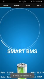
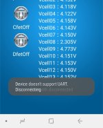
Just an update on my problem with bt not connecting. The seller finally got in contact with me sent sent me a link to download the android app which is different to the xiaoxiang app.

http://smart-bms.com/M/Support/Download/

This app does read the bms details and cell voltages however it continually disconnects and reconnects. I'm not sure if the module is faulty or if it's a different problem. I'll keep you updated with the seller's response.

20180225_112627.jpg20180225_113114.jpg

Disregard the low cell, I had a loose connection.
 
shorza said:
Just an update on my problem with bt not connecting. The seller finally got in contact with me sent sent me a link to download the android app which is different to the xiaoxiang app.

http://smart-bms.com/M/Support/Download/

This app does read the bms details and cell voltages however it continually disconnects and reconnects. I'm not sure if the module is faulty or if it's a different problem. I'll keep you updated with the seller's response.

20180225_112627.jpg20180225_113114.jpg

Disregard the low cell, I had a loose connection.

Excellent...wonder what is different. Thanks for posting this link.
 
ElectricGod said:
You are NOT liking the BT poling current right? The sleep current is already really low.
if you follow my detailed posts about how much capacity the BMS sucks from the battery over a few days, then this can only be the combined standby/polling current. maybe it's polling all the time? i don't know...
the BMS draws around 0.6mA when OFF (or not active, or whatever you call it). this is too much and leads to 0.2V drain of the pack over a month.
can anyone confirm that?
 
izeman said:
ElectricGod said:
10x 3607 will have a total resistance of 1mOhm and total heat of 3,6W and each FET sees a load of 6A ->
heat dissipated per FET will be P = I² * R = 6² * 0,0087 = 0,3W which is well within it's free air operation mode.

do you see any mistake in my calculations?

You have 2 sets of mosfets, not 10 in parallel. There's 5 for charge and 5 for discharge. So at 7.85mOhm Rds each, that's really 1.57 mOhms total Rds per set or if you are using C- for charge and discharge, then double that...3.14 mOhms. Otherwise, I don't have a problem with your math.

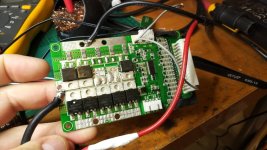
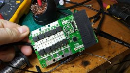
if i check how everything is connected i can see there are 2 banks of 5 FETs on top, and the same at the bottom.
the banks on top and bottom are paralleled. G/D/S are all connected to each other. on side is charge, the other is discharge.
but i still don't understand how this should work.
one side is C-, the other is B- and in the middle is P-. the only side with shunts is the B-. so this side is clear. the BMS uses the same shunts to measure charging and discharging current.
then it can turn on the two FET banks independently. those are 2x 10 FETs in parallel. no idea how 5 single FETs on the top side could be turned on/off w/o switching the bank on the bottom side as well as they are hardcoded to each other.


IMG_20180225_094510.jpg


IMG_20180225_094517.jpg
 
shorza said:
Just an update on my problem with bt not connecting. The seller finally got in contact with me sent sent me a link to download the android app which is different to the xiaoxiang app.

http://smart-bms.com/M/Support/Download/
great find. thank. unfortunately this app doesn't find any BMS with my mix2 either.
 
just wondering for you math wizards:

how much power does shitty mosfets like the ones mentioned above acutally consume on a decently sized battery (lets say 2kWh) at 48V at 25A continous and how does that compare to the "proper stuff"?
one can spend 50 bucks on proper mosfets on a BMS worth 40 but if the gains are good (or bad) then there should be a transistion point were having good mosfets actually pays off.
 
flippy said:
just wondering for you math wizards:

how much power does shitty mosfets like the ones acutally consume on a decently sized battery (lets say 2kWh) at 48V at 20A continous and how does that compare to the "proper stuff"?
one can spend 50 bucks on proper mosfets on a BMS worth 40 but if the gains are good (or bad) then there should be a transistion point were having good mosfets actually pays off.

you're missing the point. it's not reduced range we are concerned about, but the lower the internal resistance of a mosfet is (RDSon), the lower are it's losses and the higher is the current they can carry w/o getting HOT.
a rule of thumb says, that a to220 case can shed around 1W of heat w/o heat sink, not attached to anything. so if it produces let's say 2W it will get freaking hot, maybe up to a point where it will self destruct.
so using genuine FETs will make your BMS (and controller) capable of more power and run cooler.
 
izeman said:
ElectricGod said:
You are NOT liking the BT poling current right? The sleep current is already really low.
if you follow my detailed posts about how much capacity the BMS sucks from the battery over a few days, then this can only be the combined standby/polling current. maybe it's polling all the time? i don't know...
the BMS draws around 0.6mA when OFF (or not active, or whatever you call it). this is too much and leads to 0.2V drain of the pack over a month.
can anyone confirm that?

I'm not seeing this issue. I did the same test as you and I'm good. Current draw is very low. I do see cyclic current bumps when polling happens, but it's still very low. Maybe your BMS has a leaking cap or some other issue?
 
izeman said:
shorza said:
Just an update on my problem with bt not connecting. The seller finally got in contact with me sent sent me a link to download the android app which is different to the xiaoxiang app.

http://smart-bms.com/M/Support/Download/
great find. thank. unfortunately this app doesn't find any BMS with my mix2 either.

Same here...does not find my BMS's at all.
 
@izeman - I think the best way to install it is with the battery connection in the middle. You lose out on charge current measurement which isn't likely all that important anyway.
However it ensures only one bank of FETs between the motor and batteries, while maintaining independent charge and discharge protection.
I tried it like that yesterday and it worked fine for discharge anyway, I haven't connected the charger through it just yet.
 
flippy said:
just wondering for you math wizards:

how much power does shitty mosfets like the ones mentioned above acutally consume on a decently sized battery (lets say 2kWh) at 48V at 25A continous and how does that compare to the "proper stuff"?
one can spend 50 bucks on proper mosfets on a BMS worth 40 but if the gains are good (or bad) then there should be a transistion point were having good mosfets actually pays off.

Good mosfets always pay off! OK...that was a bit too black and white. hahaha

But seriously, "good" is a matter of perspective. Do Chinese mosfets work? Yes they do. What I can tell you is that Chinese mosfets have much less tolerance for over loads or any form of abuse than the legit parts do. It's not uncommon for Chinese mosfets to be slower or to have a higher Rds or not handle the rated wattage and current of the exact same part from a legit source. The real parts from legit sources will be the best option. I'm a bit of a stickler about components. I have lots of legit IRF4110's that I've pulled out of controllers and replaced with better mosfets such as the AOT290. Can you get away with NOT upgrading mosfets? Sure you can, but if you want optimal performance, then you want the best mosfets too.

The IRF4110 is a decent mosfet, so is the IRF4115, but in my opinion, they are average. There are better mosfets. In 100 volts, the IRF4110 is average, the AOT290 is much better and the CSD19536KCS is the best. In 150 volts the IRF4115 has been used extensively, but it's second best to the AOT2500 which is the best in 150 volts. A controller with IRF4110's in it or IRF4115's get upgraded to better mosfets if I have any intention of keeping that controllert. I want to be able to maximize current handling and reduce heat and losses to the lowest I can achieve. AS a result I build 12 fet controllers that continuously and reliably do 4KW and above. That's what good mosfets get you and what cheap ones will never achieve. In a BMS it is no different and exactly why I pulled the HY3410's out and replaced them!

I mess with LED's a good bit. Chinese XML's, XP-L2's or XHP70.x are crap compared to real CREE LED's. They won't be as bright for the same voltage and current and can't handle any use above specs at all. A real CREE LED can always handle an extra 20% more voltage and that usually means 2-3X more current than spec with no harm to the LED. The Chinese LED's just burn out.

That's legit and good quality parts for you!
 
izeman said:
izeman said:
ElectricGod said:
10x 3607 will have a total resistance of 1mOhm and total heat of 3,6W and each FET sees a load of 6A ->
heat dissipated per FET will be P = I² * R = 6² * 0,0087 = 0,3W which is well within it's free air operation mode.

do you see any mistake in my calculations?

You have 2 sets of mosfets, not 10 in parallel. There's 5 for charge and 5 for discharge. So at 7.85mOhm Rds each, that's really 1.57 mOhms total Rds per set or if you are using C- for charge and discharge, then double that...3.14 mOhms. Otherwise, I don't have a problem with your math.

if i check how everything is connected i can see there are 2 banks of 5 FETs on top, and the same at the bottom.
the banks on top and bottom are paralleled. G/D/S are all connected to each other. on side is charge, the other is discharge.
but i still don't understand how this should work.
one side is C-, the other is B- and in the middle is P-. the only side with shunts is the B-. so this side is clear. the BMS uses the same shunts to measure charging and discharging current.
then it can turn on the two FET banks independently. those are 2x 10 FETs in parallel. no idea how 5 single FETs on the top side could be turned on/off w/o switching the bank on the bottom side as well as they are hardcoded to each other.


IMG_20180225_094510.jpg


IMG_20180225_094517.jpg

I thought you had mosfets on only one side of the board, not both...aka 5 fets for charging and 5 for discharging. Looking at your pictures, I see what you mean. 10 fets for charge and 10 for discharge. The 2 sets of mosfets do turn on and off independently. Ironically current flow direction is easily detected. I'm NOT using the C- mosfets and my BMS knows it is charging vs discharging. The CPU should be able to do charge limiting via 1 set of mosfets. There really is no need for the C- mosfets under any circumstance. I really don't know why there are 2 sets in a typical BMS when one set is enough.

The discharge mosfets under typical situations should only shut off if current draw while discharging gets above the set limit. The charge mosfets...same thing. There's no time when you are charging and discharging at the same time so both sets of mosfets turning off is improbable.

I have never seen a BMS that had dual sets of shunts. There's no real point. The charge mosfets dump current through the discharge mosfets, then through the shunts into the battery pack. If you charge from C- or P-, this is true...all current in or out always passes through the discharge mosfets so there's no point in having more than one set of shunts since there is only one current path in and out of the batteries.
 
izeman said:
you're missing the point. it's not reduced range we are concerned about, but the lower the internal resistance of a mosfet is (RDSon), the lower are it's losses and the higher is the current they can carry w/o getting HOT.
a rule of thumb says, that a to220 case can shed around 1W of heat w/o heat sink, not attached to anything. so if it produces let's say 2W it will get freaking hot, maybe up to a point where it will self destruct.
so using genuine FETs will make your BMS (and controller) capable of more power and run cooler.
ElectricGod said:
Good mosfets always pay off! OK...that was a bit too black and white. hahaha
trust me i am not arguing in favour of the chinese crap, granted, they have their place but i am just wondering how much power loss they acutally cause, not how shitty they are. we already know that.

just in general i ask, how much power loss does a (good or bad) BMS cause and how much can you gain in efficiency by using quality mosfets?

for example, my scooter uses about 40~45W per kilometer. (this includes 50W HID and heated gloves). if i can reduce power consumption with 2~5W it would already be profit.
 
flippy said:
for example, my scooter uses about 40~45W per kilometer. (this includes 50W HID and heated gloves). if i can reduce power consumption with 2~5W it would already be profit.
I assume you're talking Wh not W.
If you ride for one hour, and i assume some speed now of 40km/h. So thus makes 40km x 45Wh/km = 1800 Wh. And the power usage of the BMS may be reduced by 2Wh. So around one thousand of your total consumption.
Short answer: No. Better FETs will not really increase your speed.
 
izeman said:
flippy said:
for example, my scooter uses about 40~45W per kilometer. (this includes 50W HID and heated gloves). if i can reduce power consumption with 2~5W it would already be profit.
I assume you're talking Wh not W.
If you ride for one hour, and i assume some speed now of 40km/h. So thus makes 40km x 45Wh/km = 1800 Wh. And the power usage of the BMS may be reduced by 2Wh. So around one thousand of your total consumption.
Short answer: No. Better FETs will not really increase your speed.

He is outside of time...it's just watts...hahaaha.

Better fets will increase his speed and efficiency..slightly. Any loss is usually in the form of heat due to resistances. The less power you waste on resistance and heat, means the more efficient your EV is and the more power goes to the motor. Is it transcendentally improved? Well NO, but IMHO efficiency gains in mosfets are just one element among many that compel me to go with better mosfets. I do it mostly becasue then I can run harder and at higher power levels with more reliability. If I was doing it purely for efficiency, I wouldn't care very much about the mosfets.

I thought about this a bit more...losses in all steel bearings will be more than what the Chinese mosfets create. Of course I replace them with ceramics so...

I looked up another HY3410 datasheet...I think this is a knock-off of the IRF3410. So maybe my original post of 105 mOhms Rds was a bit off. Still...it's a pretty mediocre mosfet...31 amps, 39 mOhms...meh!
 
ElectricGod said:
I'm not seeing this issue. I did the same test as you and I'm good. Current draw is very low. I do see cyclic current bumps when polling happens, but it's still very low. Maybe your BMS has a leaking cap or some other issue?
Could you please do me a favor and test if the BT module is always powered. Mine sees 11V all the time.
No pulsing voltage.
 
izeman said:
ElectricGod said:
I'm not seeing this issue. I did the same test as you and I'm good. Current draw is very low. I do see cyclic current bumps when polling happens, but it's still very low. Maybe your BMS has a leaking cap or some other issue?
Could you please do me a favor and test if the BT module is always powered. Mine sees 11V all the time.
No pulsing voltage.

Yes...I can do that...it won't happen immediately. I'm working on upgrading an 18 fet motor controller ATM for MORE POWER!!! Based on what I know from doing the same thing to a 12 fet, I should see something like 6.5 - 7kw. :)

Good mosfets make that possible!

I haven't looked at all, but can you find the actual BT module used on these BMS? We want the specs and pin out for it. There's likely to be an enable pin and a sleep pin on the module. Power is likely to stay on all the time and the enable and sleep wires put it in low power mode.
 
Back
Top