ElectricGod said:
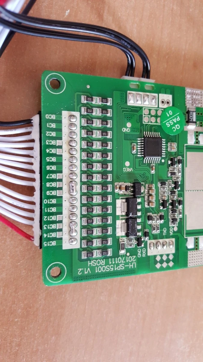
This is truly confounding! This is a 32S BMS. That means it realistically needs to handle upwards of 140 volts depending on cell chemistry. So why does it have 100 volt mosfets (HY45N10's) on the C- side? Why no access to P- where it has 150 volt IRF4115's? There is no part of 100 volt mosfets that are OK in a 32S BMS designed for 140 volt continuous operation. I can't imagine what the manufacturer was thinking!
flippy said:
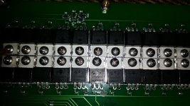
if you look further back you can see that the C- mosfets are different and not rated for the voltage unlike the B- side.
Yes the thing with those 100V FET's is indeed confusing, but if you think hard about it there should not be a problem, because the maximum voltage those C- FET's should ever see is just the voltage difference between a full and empty battery (if the charger gets connected).
Thats the way it works and i don't think the manufacturer would make such big mistake.
In case of 32S LiIon it would mean about 135V (when fully charged) minus 64V (2V per cell) if the battery is completely discharged which makes a difference of 71V and this is below the rating.
There is still the question why they were using the 100V HY045N10 instead of the IRF4115 ?
-> for lowering the losses!
The HY have 4,5 mOhm Rds while the IRF with it's 9,3 mOhm have more than twice the resistance.
So the C- FET's will produce less than half of the heat as the P- FET's do.
Or with other words: if you attach the load to C- (like described), than the accruing heat losses will be only about 50% more instead of attaching it between the two groups.


")