dak664
1 kW
- Joined
- Aug 17, 2008
- Messages
- 317
Following enso's suggestion I am starting this thread to split off discussion of BMSs from pack building.
My experience is limited to the two headway BMSs I received with the 36 cells through the ES May group purchase. Since I have three 12S1P packs I wanted to see how essential the BMS would be and whether or not it could be swapped between packs for occasional balancing. So far I think that is possible, although an internal BMS is safer and more convenient and I suspect prices will soon drop to the point where it would be silly not to include one. I have great hopes for Atmel's ATA6870/71 stackable 6 cell monitors for a few dollars each, announced in Feburary and perhaps soon available retail.
The BMS has three main functions:
1) Stop discharge if any cell voltage gets too low, by signaling the motor controller, disconnecting it, or both.
2) Stop charge if any cell voltage gets too high, by signaling the charger, disconnecting it, or both.
3) Limit current through cells that are fully charged, so the others can catch up.
As I understand it the Headway BMS disconnects the pack on any cell voltage too low <2000mv or too high >3900mv, and bypasses through 20 ohm resistors when the cell voltage goes above 3650mv. Once a cell goes into bypass, charging currents above I=E/R=3900mv/20ohm=~195 ma will cause that cell to trigger a pack disconnect. Even when disconnected, the bypass will continue to bleed the voltage down to 3650mv. At some point (I don't know when) the pack will reconnect, all cells will get another burst of current, the overvoltaged cell will shut the pack down, and so on until the cells will eventually become balanced. If the cells are near balance and the charger has the correct current taper then the charging current will be below 195 ma when the first cell goes into bypass at 3650mv, so the pack will never shut down and all cells will quickly equalize. Ideally the charger will then shut itself off, although that is not essential as long as the BMS board doesn't get too hot from bypassing all the current around all the cells.
It appears that once balanced all this will work smoothly until a cell goes really bad. However my cells as shipped were nowhere near balance; when I made the initial charge at two amps, after about an hour the BMS disconnected. Subsequently the BMS would disconnect any time I put more than ~180ma through the pack. Though the Bionx charger I was using had a conservative current taper, going to zero at 41.8 volts, the cells still at 3300-3400 millivolts made the total pack voltage <41 volts even when one cell was 3.9 volts. Adding a series resistor of 10 ohms reduced the current to 100ma and allowed continuous charging for a day to finally equalize the pack. I call this pack "alpha", and have been using it daily for a 20km ride, recharging with the Bionx charger which cuts off around 3500mv per cell, before any Headway shunts activate.
I had been working on solar buck/boost chargers for 12/36 volt lead-acid batteries, so had a bunch of ATTiny85's I could string together for monitoring of individual cells. They communicate through infrared diodes using a method similar to TV remote controls; the infrared receiver is another ATTiny85 that acts as a USB keyboard so it can "type" the voltages into a laptop. Here is the monitoring system on a breadboard:
View attachment 1
The splitter cable I hacked together to connect it together with the headway BMS, well-potted in epoxy (I hope!) under the black tape:
View attachment connector.jpg
And the input to the laptop:
View attachment laptop_logger.jpg
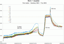
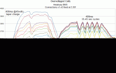
More about this on another thread, I'll post the firmware once I get it better documented. The Tinys are rated to sink ~60 milliamps total so can also be used to shunt a small amount of current around charged cells. Since I am a conservative sort of guy I've set the Tiny bypass voltage to 3.5 volts, so as long as the current is small enough the Headway BMS bypasses won't activate. I've left out a bypass resistor on this protoboard version (ran out of pads to connect it!) so it only sinks 30ma. Bear this in mind when looking at the charging graphs, below 30ma the cell voltages tend to 3500mv, at higher currents they can go up to the Headway 3650mv trips, and above 180ma they can go up to the pack trip of 3900 mv.
So here's a final boinx charge plus two equalize charges on pack alpha after 23 cycles at 230 watt hours on just the bionx charger. It appears that three cells have lower capacity even though they track the voltage pretty well. I'd have to raise the power supply voltage to ~44.5 volts to get them to fully charge, or alternately a few cycles of allowing the Tinys to bleed back to 3.5 volts should do it.

Anyway this is my understanding at present, I am still learning, could be totally wrong, and hope to learn from others here.
My experience is limited to the two headway BMSs I received with the 36 cells through the ES May group purchase. Since I have three 12S1P packs I wanted to see how essential the BMS would be and whether or not it could be swapped between packs for occasional balancing. So far I think that is possible, although an internal BMS is safer and more convenient and I suspect prices will soon drop to the point where it would be silly not to include one. I have great hopes for Atmel's ATA6870/71 stackable 6 cell monitors for a few dollars each, announced in Feburary and perhaps soon available retail.
The BMS has three main functions:
1) Stop discharge if any cell voltage gets too low, by signaling the motor controller, disconnecting it, or both.
2) Stop charge if any cell voltage gets too high, by signaling the charger, disconnecting it, or both.
3) Limit current through cells that are fully charged, so the others can catch up.
As I understand it the Headway BMS disconnects the pack on any cell voltage too low <2000mv or too high >3900mv, and bypasses through 20 ohm resistors when the cell voltage goes above 3650mv. Once a cell goes into bypass, charging currents above I=E/R=3900mv/20ohm=~195 ma will cause that cell to trigger a pack disconnect. Even when disconnected, the bypass will continue to bleed the voltage down to 3650mv. At some point (I don't know when) the pack will reconnect, all cells will get another burst of current, the overvoltaged cell will shut the pack down, and so on until the cells will eventually become balanced. If the cells are near balance and the charger has the correct current taper then the charging current will be below 195 ma when the first cell goes into bypass at 3650mv, so the pack will never shut down and all cells will quickly equalize. Ideally the charger will then shut itself off, although that is not essential as long as the BMS board doesn't get too hot from bypassing all the current around all the cells.
It appears that once balanced all this will work smoothly until a cell goes really bad. However my cells as shipped were nowhere near balance; when I made the initial charge at two amps, after about an hour the BMS disconnected. Subsequently the BMS would disconnect any time I put more than ~180ma through the pack. Though the Bionx charger I was using had a conservative current taper, going to zero at 41.8 volts, the cells still at 3300-3400 millivolts made the total pack voltage <41 volts even when one cell was 3.9 volts. Adding a series resistor of 10 ohms reduced the current to 100ma and allowed continuous charging for a day to finally equalize the pack. I call this pack "alpha", and have been using it daily for a 20km ride, recharging with the Bionx charger which cuts off around 3500mv per cell, before any Headway shunts activate.
I had been working on solar buck/boost chargers for 12/36 volt lead-acid batteries, so had a bunch of ATTiny85's I could string together for monitoring of individual cells. They communicate through infrared diodes using a method similar to TV remote controls; the infrared receiver is another ATTiny85 that acts as a USB keyboard so it can "type" the voltages into a laptop. Here is the monitoring system on a breadboard:
View attachment 1
The splitter cable I hacked together to connect it together with the headway BMS, well-potted in epoxy (I hope!) under the black tape:
View attachment connector.jpg
And the input to the laptop:
View attachment laptop_logger.jpg
More about this on another thread, I'll post the firmware once I get it better documented. The Tinys are rated to sink ~60 milliamps total so can also be used to shunt a small amount of current around charged cells. Since I am a conservative sort of guy I've set the Tiny bypass voltage to 3.5 volts, so as long as the current is small enough the Headway BMS bypasses won't activate. I've left out a bypass resistor on this protoboard version (ran out of pads to connect it!) so it only sinks 30ma. Bear this in mind when looking at the charging graphs, below 30ma the cell voltages tend to 3500mv, at higher currents they can go up to the Headway 3650mv trips, and above 180ma they can go up to the pack trip of 3900 mv.
So here's a final boinx charge plus two equalize charges on pack alpha after 23 cycles at 230 watt hours on just the bionx charger. It appears that three cells have lower capacity even though they track the voltage pretty well. I'd have to raise the power supply voltage to ~44.5 volts to get them to fully charge, or alternately a few cycles of allowing the Tinys to bleed back to 3.5 volts should do it.

Anyway this is my understanding at present, I am still learning, could be totally wrong, and hope to learn from others here.


