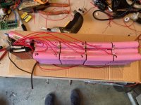
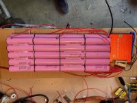
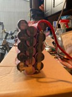
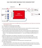
I need help wiring a BMS with a 48v 13s 4p?? battery (see pictures).
I attempted to replace a bad BMS with a Daly 13s 48v and the final test (step 3 in wiring diagram) to test the battery voltage and BMS output voltage didn't match (they should if wired properly). The B- and B+ was 52.2v and B+ and P- was 4.1 volts.
I ran the BMS wires by matching the cable runs with the original connector and labeled the battery 1 thru 12. I confirmed each cable run was between 4.04 and 4.08 volts at the connector pins and the total voltage was 52.2.
Where have I gone wrong with my wiring sequence?


